- Manuals
- Brands
- Omron Manuals
- I/O Systems
- CJ2M-CPU Series
Manuals and User Guides for Omron CJ2M-CPU Series. We have 13 Omron CJ2M-CPU Series manuals available for free PDF download: Reference Manual, Instruction & Reference Manual, User Manual, Connection Manual, Replacement Manual
OMRON CJ2M-CPU Series Reference Manual (1308 pages)
Brand: OMRON
|
Category: Controller
|
Size: 35.57 MB
Table of Contents
-
Table of Contents
37
-
About this Manual
7
-
Intended Audience
8
-
Related Manuals
26
-
Safety Precautions
29
-
General Precautions
30
-
Application Precautions
32
-
Table of Contents
37
-
-
Basic Understanding of Instructions
39
-
Basic Understanding of Instructions
40
-
Instruction Location and Execution Conditions
42
-
-
Specifying Operands
49
-
Specifying Operands
50
-
-
Data Formats
57
-
-
Section 2 Summary of Instructions
61
-
Summary of Instructions
61
-
Instruction Set and CPU Unit Support for Individual Instructions
62
-
Instruction Functions
71
-
Sequence Input Instructions
71
-
Sequence Output Instructions
73
-
Sequence Control Instructions
76
-
Timer and Counter Instructions
80
-
Comparison Instructions
85
-
Data Movement Instructions
89
-
Data Shift Instructions
92
-
Increment/Decrement Instructions
96
-
Symbol Math Instructions
97
-
2-2-10 Conversion Instructions
102
-
2-2-11 Logic Instructions
110
-
2-2-12 Special Math Instructions
112
-
2-2-13 Floating-Point Math Instructions
113
-
2-2-14 Double-Precision Floating-Point Instructions
118
-
Table Data Processing Instructions
122
-
Tracking Instructions
127
-
-
2-2-17 Data Control Instructions
129
-
2-2-18 Subroutine Instructions
133
-
2-2-19 Interrupt Control Instructions
134
-
(CJ2M-CPU@@ and CJ1M-CPU21/22/23 Only)
136
-
2-2-20 High-Speed Counter and Pulse Output Instructions
136
-
2-2-21 Step Instructions
138
-
2-2-22 Basic I/O Unit Instructions
138
-
2-2-23 Serial Communications Instructions
142
-
2-2-24 Network Instructions
144
-
2-2-25 File Memory Instructions
147
-
2-2-26 Display Instructions
149
-
2-2-27 Clock Instructions
149
-
2-2-28 Debugging Instructions
150
-
2-2-29 Failure Diagnosis Instructions
151
-
2-2-30 Other Instructions
152
-
2-2-31 Block Programming Instructions
153
-
2-2-32 Text String Processing Instructions
159
-
2-2-33 Task Control Instructions
162
-
(CPU Unit Ver. 3.0 or Later and CJ2 CPU Units Only)
163
-
Model Conversion Instructions
163
-
2-2-35 Special Function Block Instructions
164
-
2-2-36 SFC Instructions
165
-
-
Section 3 Instructions
167
-
Instructions
167
-
Notation and Layout of Instruction Descriptions
173
-
Condition Flags
175
-
-
Sequence Input Instructions
176
-
Ld/Ld Not
178
-
And/And Not
180
-
Or/Or Not
182
-
And Ld/Or Ld
184
-
Not
187
-
Up/Down
188
-
Ld Tst/Ld Tstn
190
-
And Tst/And Tstn
192
-
Or Tst/Or Tstn
194
-
Out/Out Not
196
-
Sequence Output Instructions
196
-
Keep
200
-
Difu
204
-
Difd
206
-
Set/Rset
208
-
Seta/Rsta
210
-
Setb/Rstb
212
-
Outb
214
-
Sequence Control Instructions
216
-
End
219
-
Nop
220
-
Il/Ilc
221
-
Milh/Milr/Milc
225
-
Jmp/Jme
234
-
Cjp/Cjpn
237
-
Jmp0/Jme0
240
-
For/Next
243
-
Break
246
-
Timer and Counter Instructions
247
-
Tim/Timx
255
-
Timh/Timhx
259
-
Tmhh/Tmhhx
263
-
Timu/Timux
266
-
Tmuh/Tmuhx
269
-
Ttim/Ttimx
272
-
Timl/Timlx
275
-
Mtim/Mtimx
278
-
Cnt/Cntx
282
-
Cntr/Cntrx
285
-
Cnr/Cnrx
288
-
Trset
290
-
Comparison Instructions
291
-
Dt, <>Dt, <Dt, <=Dt, >Dt, >=Dt
295
-
Cmp/Cmpl
299
-
Cps/Cpsl
302
-
Mcmp
305
-
Tcmp
307
-
Bcmp
309
-
Bcmp2
311
-
Zcp/Zcpl
314
-
Data Movement Instructions
321
-
Mov/Movl
321
-
Mvn/Mvnl
324
-
Movb
326
-
Movd
328
-
Xfrb
330
-
Xfer
332
-
Bset
334
-
Xchg/Xcgl
336
-
Dist
338
-
Coll
340
-
Movr/Movrw
342
-
Data Shift Instruction
345
-
Sft
345
-
Sftr
347
-
Asft
349
-
Wsft
351
-
Asl/Asll
353
-
Asr/Asrl
355
-
Rol/Roll
357
-
Rlnc/Rlnl
359
-
Ror/Rorl
361
-
Rrnc/Rrnl
363
-
Sld/Srd
365
-
Nsfl/Nsfr
367
-
Nasl/Nsll
370
-
Nasr/Nsrl
373
-
Increment/Decrement Instructions
376
-
B/++Bl
382
-
Symbol Math Instructions
388
-
C/+Cl
390
-
B/+Bl
392
-
Bc/+Bcl
394
-
C/-Cl
400
-
B/-Bl
403
-
Bc/-Bcl
406
-
U/*Ul
410
-
B/*Bl
412
-
U, /Ul
416
-
B, /Bl
418
-
Bin/Binl
420
-
Conversion Instructions
420
-
Bcd/Bcdl
422
-
Neg/Negl
425
-
Sign
427
-
Mlpx
429
-
Dmpx
434
-
Asc
439
-
Hex
443
-
Line
448
-
Colm
450
-
Bins/Bisl
452
-
Bcds/Bdsl
457
-
Gry
461
-
Gray_Bin/Gray_Binl
466
-
Bin_Gray/Bin_Grayl
468
-
Str4/Str8/Str16
470
-
Num4/Num8/Num16
473
-
Andw/Andl
476
-
Logic Instructions
476
-
Orw/Orwl
478
-
Xorw/Xorl
480
-
Xnrw/Xnrl
482
-
Com/Coml
484
-
Rotb
486
-
Special Math Instructions
486
-
Root
488
-
Apr
491
-
Fdiv
500
-
Application Example
502
-
-
Bcnt
503
-
Floating-Point Math Instructions
505
-
Fix/Fixl
510
-
Flt/Fltl
512
-
F, -F, *F, /F
514
-
Rad
518
-
Deg
520
-
Sin/Cos/Tan
522
-
Sinq/Cosq/Tanq
525
-
Asin/Acos/Atan
529
-
Sqrt
532
-
Exp
534
-
Log
536
-
Pwr
538
-
F, <>F, <F, <=F, >F, >=F
540
-
Fstr
543
-
Fval
548
-
Movf
552
-
Double-Precision Floating-Point Instructions
553
-
Fixd/Fixld
559
-
Dbl/Dbll
561
-
+D, -D, D, /D
563
-
Radd
566
-
Degd
568
-
Sind/Cosd/Tand
570
-
Asind/Acosd/Atand
573
-
Sqrtd
576
-
Expd
578
-
Logd
580
-
Pwrd
582
-
D, <>D, <D, <=D, >D, >=D
584
-
Table Data Processing Instructions
587
-
Sset
592
-
Push
595
-
Lifo/Fifo
597
-
Snum
601
-
Sread
603
-
Swrit
606
-
Sins
609
-
Sdel
612
-
DIM
615
-
Setr
617
-
Getr
619
-
Srch
621
-
Related Auxiliary Area Words and Bits
622
-
-
Swap
624
-
Max/Min
626
-
Maxl
630
-
Maxf
633
-
Maxd
635
-
Minl
637
-
Minf
639
-
Mind
641
-
Sum
643
-
Fcs
646
-
Tracking Instructions
649
-
Rsrch<, Rsrch<=, Rsrch=, Rsrch>, Rsrch
656
-
Rsrch2<, Rsrch2<=, Rsrch2=, Rsrch2>, Rsrch2
662
-
Rsrch4<, Rsrch4<=, Rsrch4=, Rsrch4>, Rsrch4
665
-
Rsort
668
-
Rsort2
672
-
Rsort4
675
-
Data Control Instructions
678
-
Pid
678
-
Performance Specifications
680
-
Calculation Method
680
-
-
Pidat
689
-
Lmt
696
-
Band
698
-
Zone
701
-
Tpo
703
-
Parameter Settings
705
-
-
Scl
710
-
Scl2
714
-
Scl3
718
-
Avg
721
-
Subroutine Instruction
724
-
Subroutines
724
-
Sbs
725
-
Mcro
731
-
Sbn/Ret
734
-
Gsbs
737
-
Gsbn/Gret
743
-
Interrupt Control Instructions
746
-
Scheduled Interrupts
748
-
-
Advertisement
OMRON CJ2M-CPU Series Reference Manual (1282 pages)
Brand: OMRON
|
Category: Controller
|
Size: 32.25 MB
Table of Contents
-
Table of Contents
35
-
Basic Understanding of Instructions
37
-
Basic Understanding of Instructions
38
-
Specifying Operands
47
-
Data Formats
54
-
-
Section 2 Summary of Instructions
57
-
Summary of Instructions
57
-
Instruction Set and CPU Unit Support for Individual Instructions
58
-
Instruction Functions
67
-
Sequence Input Instructions
67
-
Sequence Output Instructions
69
-
Sequence Control Instructions
72
-
Timer and Counter Instructions
76
-
Comparison Instructions
81
-
Data Movement Instructions
85
-
Data Shift Instructions
88
-
Increment/Decrement Instructions
92
-
Symbol Math Instructions
93
-
2-2-10 Conversion Instructions
98
-
Logic Instructions
106
-
2-2-12 Special Math Instructions
108
-
Floating-Point Math Instructions
109
-
Double-Precision Floating-Point Instructions
114
-
2-2-17 Data Control Instructions
125
-
2-2-18 Subroutine Instructions
129
-
Interrupt Control Instructions
130
-
(CJ1M-CPU21/22/23 Only)
132
-
Basic I/O Unit Instructions
134
-
Step Instructions
134
-
Serial Communications Instructions
138
-
Network Instructions
140
-
File Memory Instructions
143
-
2-2-26 Display Instructions
145
-
2-2-27 Clock Instructions
145
-
2-2-28 Debugging Instructions
146
-
2-2-29 Failure Diagnosis Instructions
147
-
Other Instructions
148
-
Block Programming Instructions
149
-
Text String Processing Instructions
155
-
2-2-33 Task Control Instructions
158
-
Model Conversion Instructions (CPU Unit Ver. 3.0 or Later and CJ2 CPU Units Only)
159
-
Special Function Block Instructions
160
-
2-2-36 SFC Instructions
161
-
-
Section 3 Instructions
163
-
Instructions
163
-
Notation and Layout of Instruction Descriptions
169
-
Sequence Input Instructions
172
-
Ld/Ld Not
174
-
And/And Not
176
-
Or/Or Not
178
-
And Ld/Or Ld
180
-
Not
183
-
Up/Down
184
-
Ld Tst/Ld Tstn
186
-
And Tst/And Tstn
188
-
Or Tst/Or Tstn
190
-
Out/Out Not
192
-
Sequence Output Instructions
192
-
Keep
196
-
Difu
200
-
Difd
202
-
Set/Rset
204
-
Seta/Rsta
206
-
Setb/Rstb
208
-
Outb
210
-
Sequence Control Instructions
212
-
End
215
-
Nop
216
-
Il/Ilc
217
-
Milh/Milr/Milc
221
-
Jmp/Jme
230
-
Cjp/Cjpn
233
-
Jmp0/Jme0
236
-
For/Next
239
-
Break
242
-
Timer and Counter Instructions
243
-
Tim/Timx
251
-
Timh/Timhx
255
-
Tmhh/Tmhhx
259
-
Timu/Timux
262
-
Tmuh/Tmuhx
265
-
Ttim/Ttimx
268
-
Timl/Timlx
271
-
Mtim/Mtimx
274
-
Cnt/Cntx
278
-
Cntr/Cntrx
281
-
Cnr/Cnrx
284
-
Trset
286
-
Comparison Instructions
287
-
Dt, <>Dt, <Dt, <=Dt, >Dt, >=Dt
291
-
Cmp/Cmpl
295
-
Cps/Cpsl
298
-
Mcmp
301
-
Tcmp
303
-
Bcmp
305
-
Bcmp2
307
-
Zcp/Zcpl
310
-
Data Movement Instructions
317
-
Mov/Movl
317
-
Mvn/Mvnl
320
-
Movb
322
-
Movd
324
-
Xfrb
326
-
Xfer
328
-
Bset
330
-
Xchg/Xcgl
332
-
Dist
334
-
Coll
336
-
Movr/Movrw
338
-
Data Shift Instruction
341
-
Sft
341
-
Sftr
343
-
Asft
345
-
Wsft
347
-
Asl/Asll
349
-
Asr/Asrl
351
-
Rol/Roll
353
-
Rlnc/Rlnl
355
-
Ror/Rorl
357
-
Rrnc/Rrnl
359
-
Sld/Srd
361
-
Nsfl/Nsfr
363
-
Nasl/Nsll
366
-
Nasr/Nsrl
369
-
Increment/Decrement Instructions
372
-
B/++Bl
378
-
Symbol Math Instructions
384
-
C/+Cl
386
-
B/+Bl
388
-
Bc/+Bcl
390
-
C/-Cl
396
-
B/-Bl
399
-
Bc/-Bcl
402
-
U/*Ul
406
-
B/*Bl
408
-
U, /Ul
412
-
B, /Bl
414
-
Bin/Binl
416
-
Conversion Instructions
416
-
Bcd/Bcdl
418
-
Neg/Negl
421
-
Sign
423
-
Mlpx
425
-
Dmpx
430
-
Asc
435
-
Hex
439
-
Line
444
-
Colm
446
-
Bins/Bisl
448
-
Bcds/Bdsl
453
-
Gry
457
-
Gray_Bin/Gray_Binl
462
-
Bin_Gray/Bin_Grayl
464
-
Str4/Str8/Str16
466
-
Num4/Num8/Num16
469
-
Andw/Andl
472
-
Logic Instructions
472
-
Orw/Orwl
474
-
Xorw/Xorl
476
-
Xnrw/Xnrl
478
-
Com/Coml
480
-
Rotb
482
-
Special Math Instructions
482
-
Root
484
-
Apr
487
-
Fdiv
496
-
Bcnt
499
-
Floating-Point Math Instructions
501
-
Fix/Fixl
506
-
Flt/Fltl
508
-
F, -F, *F, /F
510
-
Rad
514
-
Deg
516
-
Sin/Cos/Tan
518
-
Sinq/Cosq/Tanq
521
-
Asin/Acos/Atan
525
-
Sqrt
528
-
Exp
530
-
Log
532
-
Pwr
534
-
F, <>F, <F, <=F, >F, >=F
536
-
Fstr
539
-
Fval
544
-
Movf
548
-
Double-Precision Floating-Point Instructions
549
-
Fixd/Fixld
555
-
Dbl/Dbll
557
-
+D, -D, D, /D
559
-
Radd
562
-
Degd
564
-
Sind/Cosd/Tand
566
-
Asind/Acosd/Atand
569
-
Sqrtd
572
-
Expd
574
-
Logd
576
-
Pwrd
578
-
D, <>D, <D, <=D, >D, >=D
580
-
Table Data Processing Instructions
583
-
Sset
588
-
Push
591
-
Lifo/Fifo
593
-
Snum
597
-
Sread
599
-
Swrit
602
-
Sins
605
-
Sdel
608
-
DIM
611
-
Setr
613
-
Getr
615
-
Srch
617
-
Swap
620
-
Max/Min
622
-
Maxl
626
-
Maxf
629
-
Maxd
631
-
Minl
633
-
Minf
635
-
Mind
637
-
Sum
639
-
Fcs
642
-
Tracking Instructions
645
-
Rsrch<, Rsrch<=, Rsrch=, Rsrch>, Rsrch
652
-
Rsrch2<, Rsrch2<=, Rsrch2=, Rsrch2>, Rsrch2
658
-
Rsrch4<, Rsrch4<=, Rsrch4=, Rsrch4>, Rsrch4
661
-
Rsort
664
-
Rsort2
668
-
Rsort4
671
-
Data Control Instructions
674
-
Pid
674
-
Pidat
685
-
Lmt
692
-
Band
694
-
Zone
697
-
Tpo
699
-
Scl
706
-
Scl2
710
-
Scl3
714
-
Avg
717
-
Subroutine Instruction
720
-
Subroutines
720
-
Sbs
721
-
Mcro
727
-
Sbn/Ret
730
-
Gsbs
733
-
Gsbn/Gret
739
-
Interrupt Control Instructions
742
-
Msks
745
-
Mskr
751
-
Cli
755
-
High-Speed Counter/Pulse Output Instructions
763
-
Ini
763
-
Prv
766
-
Prv2
771
-
Ctbl
774
-
Sped
778
-
Puls
782
-
Pls2
784
-
Acc
790
-
Org
795
-
Pwm
798
-
Step Instructions
800
-
Snxt/Step
801
-
Basic I/O Unit Instructions
811
-
Iorf
811
-
Fiorf
814
-
Dlnk
817
-
Sdec
821
-
Dsw
824
-
Tky
828
-
Hky
831
-
Mtr
835
-
7Seg
839
-
Iord
856
-
Iowr
859
-
Serial Communications Instructions
862
-
Pmcr
864
-
Txd
871
-
Rxd
877
-
Txdu
886
-
Rxdu
892
-
Stup
912
-
Omron CJ2M-CPU Series Instruction & Reference Manual (1234 pages)
Brand: Omron
|
Category: Controller
|
Size: 21.61 MB
Table of Contents
-
Table of Contents
33
-
Basic Understanding of Instructions
35
-
Basic Understanding of Instructions
36
-
Specifying Operands
45
-
Data Formats
53
-
Instructions (Applicable CPU Units)
57
-
Instructions
79
-
SECTION 3Notation and Layout of Instruction Descriptions
85
-
Sequence Input Instructions
88
-
Sequence Output Instructions
108
-
Sequence Control Instructions
128
-
Timer and Counter Instructions
159
-
Comparison Instructions
203
-
Data Movement Instructions
233
-
Data Shift Instruction
257
-
Increment/Decrement Instructions
288
-
Symbol Math Instructions
300
-
Conversion Instructions
332
-
Logic Instructions
388
-
Special Math Instructions
398
-
Floating-Point Math Instructions
417
-
Double-Precision Floating-Point Instructions
465
-
Table Data Processing Instructions
499
-
Tracking Instructions
561
-
Data Control Instructions
590
-
Subroutines
637
-
Interrupt Control Instructions
659
-
High-Speed Counter/Pulse Output Instructions
681
-
Step Instructions
735
-
Basic I/O Unit Instructions
746
-
Serial Communications Instructions
797
-
Network Instructions
861
-
File Memory Instructions
937
-
Display Instructions
961
-
Clock Instructions
964
-
Debugging Instructions
975
-
Failure Diagnosis Instructions
978
-
Other Instructions
999
-
Block Programming Instructions
1016
-
Text String Processing Instructions
1043
-
Task Control Instructions
1072
-
Model Conversion Instructions
1076
-
Special Function Block Instructions
1090
-
SFC Instructions
1092
-
Instruction Execution Times and Number of Steps
1103
-
CJ2 CPU Unit Instruction Execution Times and Number of Steps
1106
-
CJ1 CPU Unit Instruction Execution Times and Number of Steps
1135
-
CS-Series Instruction Execution Times and Number of Steps
1162
-
List of Instructions by Function Code
1187
-
Alphabetical List of Instructions by Mnemonic
1203
-
ASCII Code Table
1221
-
Index
1223
-
Revision History
1231
Advertisement
OMRON CJ2M-CPU Series User Manual (670 pages)
CJ2 CPU Unit Software
Brand: OMRON
|
Category: Software
|
Size: 21.02 MB
Table of Contents
-
Table of Contents
15
-
Introduction
7
-
Intended Audience
7
-
-
CJ2 CPU Unit Manuals
8
-
Manual Structure
11
-
Additional Information
11
-
-
Sections in this Manual
13
-
Table of Contents
15
-
-
-
Table of Contents
21
-
Safety Precautions
27
-
Application Precautions
31
-
Operating Environment Precautions
36
-
Regulations and Standards
37
-
Unit Versions of CJ2 CPU Units
39
-
Related Manuals
45
-
-
1 Overview
47
-
CJ2 CPU Unit Features
47
-
Overview of CJ2 CPU Units
47
-
Overview of CJ2 CPU Units
48
-
Overview
48
-
Overview
49
-
CJ2 CPU Unit Features
50
-
-
Basic Operating Procedure
58
-
-
2 Internal Memory in the CPU Unit
59
-
Memory Configuration
59
-
Overview
60
-
Memory Configuration
60
-
Built-In Flash Memory
60
-
Built-In Ram
60
-
-
Memory Areas and Stored Data
61
-
Transferring Data from a Programming Device to the CPU Unit
62
-
-
-
CPU Unit Operation
63
-
CPU Unit Operating Modes
63
-
CPU Unit Internal Operation
64
-
Overview
64
-
Startup Initialization
64
-
Cycle Time
66
-
Program Execution
66
-
I/O Refreshing
68
-
Processing at Power Interruptions
69
-
-
CPU Unit Operating Modes
70
-
Operating Modes
70
-
Checking the Operating Mode
71
-
Changing the Operating Mode
72
-
Operating Mode Details
76
-
-
-
CPU Unit Initialization
77
-
Overview of CPU Unit Initialization
78
-
CPU Unit Initial Settings
78
-
CPU Unit Initialization
78
-
Dip Switch
78
-
Plc Name
80
-
Routing Tables
81
-
-
PLC Setup
84
-
Creating I/O Tables
85
-
I/O Tables
85
-
Automatic Allocation
86
-
Manual Allocation
86
-
-
Setting Routing Tables
87
-
Routing Tables
87
-
Local Network Table
88
-
Relay Network Table
88
-
Cases in Which Routing Tables Are Required
89
-
Setting and Transferring Routing Tables
90
-
-
Setting Allocated DM Area Words for Special I/O Units and CPU Bus Units
91
-
Setting Procedure
91
-
-
CPU Bus Unit Setup Area
92
-
Setting Procedure
92
-
-
-
Understanding Programming
93
-
Programming
95
-
Programming Overview
95
-
Program Capacity
97
-
Basic Ladder Diagram Concepts
98
-
ST Language
100
-
SFC Overview
101
-
-
Tasks
103
-
Overview of Tasks
103
-
Cyclic Tasks
106
-
Cyclic Task Status
108
-
Task Control Instructions
109
-
Interrupt Tasks
112
-
External Interrupts
120
-
Designing Tasks
122
-
Flags Related to Tasks
125
-
-
Sections
132
-
Overview of Sections
132
-
-
Function Blocks
134
-
Features of Function Blocks
134
-
Function Block Specifications
136
-
-
Symbols
139
-
Overview
139
-
Types of Symbols
140
-
Variables in Function Blocks
141
-
Global Symbols
142
-
Local Symbols
142
-
Network Symbols
143
-
Network Symbols (CJ2H-CPU6@-EIP and CJ2M-CPU3@ Only)
143
-
Variables in Function Blocks
147
-
Symbol Data Types
148
-
Specifying Arrays
149
-
Automatic Address Allocation to Symbols
153
-
-
Instructions
154
-
Basic Understanding of Instructions
154
-
Instruction Conditions
155
-
Instruction Location and Execution Conditions
156
-
-
Instruction Variations
157
-
Execution Conditions
157
-
Specifying Operands
161
-
-
Specifying Operands
163
-
Data Formats
169
-
I/O Refresh Timing
173
-
Cyclic Refresh
173
-
-
Index Registers
178
-
What Are Index Registers
178
-
Using Index Registers
178
-
Processing Related to Index Registers
183
-
Monitoring Index Registers
184
-
Sharing Index and Data Registers between Tasks
185
-
-
Specifying Address Offsets
187
-
Overview
187
-
Examples of Address Offset Application
189
-
-
Checking Programs
190
-
Errors During CX-Programmer Input
190
-
Program Checks with the CX-Programmer
190
-
Debugging with the Simulator
191
-
Error Simulation Function
193
-
Program Execution Check
194
-
Other Errors
195
-
-
Precautions
197
-
Condition Flags
197
-
Special Program Sections
202
-
-
-
I/O Memory Areas
207
-
I/O Memory Areas
207
-
I/O Memory Area Overview
208
-
I/O Memory Areas
208
-
I/O Memory Area Structure
210
-
Holding I/O Memory Values
212
-
I/O Area
214
-
Input Bits
214
-
Output Bits
216
-
-
Data Link Area
219
-
Synchronous Data Refresh Area
220
-
CPU Bus Unit Area
221
-
Special I/O Unit Area
222
-
Pulse I/O Area
223
-
Serial PLC Link Area
224
-
Devicenet Area
225
-
Work Area
226
-
Holding Area
227
-
Self-Maintaining Bits
227
-
-
Auxiliary Area
229
-
Temporary Relay Area
230
-
Data Memory Area
231
-
Extended Data Memory Area
234
-
Automatic Address Allocation
234
-
File Memory
235
-
Trace Memory
235
-
-
Timer Areas
238
-
Counter Areas
240
-
Task Flags
241
-
Index Registers
242
-
Data Registers
247
-
Condition Flags
249
-
Clock Pulses
251
-

OMRON CJ2M-CPU Series User Manual (670 pages)
CJ2 CPU Unit Software
Brand: OMRON
|
Category: Software
|
Size: 19.32 MB
Table of Contents
-
Table of Contents
15
-
Introduction
7
-
Intended Audience
7
-
-
CJ2 CPU Unit Manuals
8
-
Manual Structure
11
-
Additional Information
11
-
-
Sections in this Manual
13
-
Table of Contents
15
-
-
-
Table of Contents
21
-
Safety Precautions
27
-
Application Precautions
31
-
Operating Environment Precautions
36
-
Regulations and Standards
37
-
Unit Versions of CJ2 CPU Units
39
-
Related Manuals
45
-
-
1 Overview
47
-
CJ2 CPU Unit Features
47
-
Overview of CJ2 CPU Units
47
-
Overview of CJ2 CPU Units
48
-
Overview
48
-
Overview
49
-
CJ2 CPU Unit Features
50
-
-
Basic Operating Procedure
58
-
-
2 Internal Memory in the CPU Unit
59
-
Memory Configuration
59
-
Overview
60
-
Memory Configuration
60
-
Built-In Flash Memory
60
-
Built-In Ram
60
-
-
Memory Areas and Stored Data
61
-
Transferring Data from a Programming Device to the CPU Unit
62
-
-
-
CPU Unit Operation
63
-
CPU Unit Operating Modes
63
-
CPU Unit Internal Operation
64
-
Overview
64
-
Startup Initialization
64
-
Cycle Time
66
-
Program Execution
66
-
I/O Refreshing
68
-
Processing at Power Interruptions
69
-
-
CPU Unit Operating Modes
70
-
Operating Modes
70
-
Checking the Operating Mode
71
-
Changing the Operating Mode
72
-
Operating Mode Details
76
-
-
-
CPU Unit Initialization
77
-
Overview of CPU Unit Initialization
78
-
CPU Unit Initial Settings
78
-
CPU Unit Initialization
78
-
Dip Switch
78
-
Plc Name
80
-
Routing Tables
81
-
-
PLC Setup
84
-
Creating I/O Tables
85
-
I/O Tables
85
-
Automatic Allocation
86
-
Manual Allocation
86
-
-
Setting Routing Tables
87
-
Routing Tables
87
-
Local Network Table
88
-
Relay Network Table
88
-
Cases in Which Routing Tables Are Required
89
-
Setting and Transferring Routing Tables
90
-
-
Setting Allocated DM Area Words for Special I/O Units and CPU Bus Units
91
-
Setting Procedure
91
-
-
CPU Bus Unit Setup Area
92
-
Setting Procedure
92
-
-
-
Understanding Programming
93
-
Programming
95
-
Programming Overview
95
-
Program Capacity
97
-
Basic Ladder Diagram Concepts
98
-
ST Language
100
-
SFC Overview
101
-
-
Tasks
103
-
Overview of Tasks
103
-
Cyclic Tasks
106
-
Cyclic Task Status
108
-
Task Control Instructions
109
-
Interrupt Tasks
112
-
External Interrupts
120
-
Designing Tasks
122
-
Flags Related to Tasks
125
-
-
Sections
132
-
Overview of Sections
132
-
-
Function Blocks
134
-
Features of Function Blocks
134
-
Function Block Specifications
136
-
-
Symbols
139
-
Overview
139
-
Types of Symbols
140
-
Variables in Function Blocks
141
-
Global Symbols
142
-
Local Symbols
142
-
Network Symbols
143
-
Network Symbols (CJ2H-CPU6@-EIP and CJ2M-CPU3@ Only)
143
-
Variables in Function Blocks
147
-
Symbol Data Types
148
-
Specifying Arrays
149
-
Automatic Address Allocation to Symbols
153
-
-
Instructions
154
-
Basic Understanding of Instructions
154
-
Instruction Conditions
155
-
Instruction Location and Execution Conditions
156
-
-
Instruction Variations
157
-
Execution Conditions
157
-
Specifying Operands
161
-
-
Specifying Operands
163
-
Data Formats
169
-
I/O Refresh Timing
173
-
Cyclic Refresh
173
-
-
Index Registers
178
-
What Are Index Registers
178
-
Using Index Registers
178
-
Processing Related to Index Registers
183
-
Monitoring Index Registers
184
-
Sharing Index and Data Registers between Tasks
185
-
-
Specifying Address Offsets
187
-
Overview
187
-
Examples of Address Offset Application
189
-
-
Checking Programs
190
-
Errors During CX-Programmer Input
190
-
Program Checks with the CX-Programmer
190
-
Debugging with the Simulator
191
-
Error Simulation Function
193
-
Program Execution Check
194
-
Other Errors
195
-
-
Precautions
197
-
Condition Flags
197
-
Special Program Sections
202
-
-
-
I/O Memory Areas
207
-
I/O Memory Areas
207
-
I/O Memory Area Overview
208
-
I/O Memory Areas
208
-
I/O Memory Area Structure
210
-
Holding I/O Memory Values
212
-
I/O Area
214
-
Input Bits
214
-
Output Bits
216
-
-
Data Link Area
219
-
Synchronous Data Refresh Area
220
-
CPU Bus Unit Area
221
-
Special I/O Unit Area
222
-
Pulse I/O Area
223
-
Serial PLC Link Area
224
-
Devicenet Area
225
-
Work Area
226
-
Holding Area
227
-
Self-Maintaining Bits
227
-
-
Auxiliary Area
229
-
Temporary Relay Area
230
-
Data Memory Area
231
-
Extended Data Memory Area
234
-
Automatic Address Allocation
234
-
File Memory
235
-
Trace Memory
235
-
-
Timer Areas
238
-
Counter Areas
240
-
Task Flags
241
-
Index Registers
242
-
Data Registers
247
-
Condition Flags
249
-
Clock Pulses
251
-
OMRON CJ2M-CPU Series User Manual (424 pages)
CJ2 CPU Unit Hardware
Brand: OMRON
|
Category: Processor
|
Size: 9.04 MB
Table of Contents
-
Introduction
7
-
Intended Audience
7
-
-
CJ2 CPU Unit Manuals
8
-
Manual Structure
11
-
Additional Information
11
-
-
Sections in this Manual
13
-
Table of Contents
15
-
-
Safety Precautions
23
-
Application Precautions
27
-
Operating Environment Precautions
32
-
Regulations and Standards
33
-
Unit Versions of CJ2 CPU Units
35
-
Related Manuals
41
-
Overview
43
-
-
Overview of CJ2 CPU Units
44
-
Overview
44
-
Overview
45
-
CJ2 CPU Unit Features
46
-
-
Basic Operating Procedure
54
-
Specifications
55
-
General Specifications
55
-
Performance Specifications
56
-
-
Index
57
-
Function Specifications
63
-
Basic System Configuration and Devices
71
-
Expanded System Configuration
71
-
-
-
Basic System Configuration
72
-
CPU Rack
72
-
Memory Cards
78
-
Expansion Racks
81
-
Configuration Units
84
-
Calculating Unit Current Consumption
92
-
Calculating Power Consumption
95
-
-
Expanded System Configuration
97
-
Serial Communications
97
-
System Configuration Example
98
-
Communications Networks
99
-
Nomenclature and Functions
102
-
-
-
CPU Units
102
-
CPU Section
102
-
Built-In Ethernet/Ip Section (CJ2H-CPU6@-EIP and CJ2M-CPU3@ Only)
108
-
Seven-Segment Display
109
-
-
Memory Card
113
-
Models and Specifications
113
-
Operating Procedures
113
-
Installing and Removing
114
-
-
Pulse I/O Modules (CJ2M CPU Unit Only)
117
-
Models and Specifications
117
-
Part Names and Functions
117
-
-
Serial Option Boards (CJ2M-CPU3@ Only)
120
-
Overview
120
-
-
Power Supply Units
121
-
Models and Specifications
121
-
Components
124
-
Selecting a Power Supply Unit
127
-
-
CJ-Series Basic I/O Units
128
-
Basic I/O Units with Terminal Blocks
128
-
Thirty-Two/Sixty-Four-Point Basic I/O Units with Connectors
130
-
-
I/O Control Units and I/O Interface Units
132
-
Component Names
132
-
System Configuration
132
-
Support Software
133
-
-
Omron CJ2M-CPU Series User Manual (278 pages)
SYSMAC CJ Series CPU Unit Pulse I/O Module
Brand: Omron
|
Category: I/O Systems
|
Size: 3.6 MB
Table of Contents
-
Introduction
7
-
Intended Audience
7
-
-
CJ2 CPU Unit Manuals
8
-
Manual Structure
11
-
Additional Information
11
-
-
Sections in this Manual
13
-
Table of Contents
15
-
-
Safety Precautions
23
-
Application Precautions
27
-
Operating Environment Precautions
32
-
Regulations and Standards
33
-
Unit Versions of CJ2 CPU Units
36
-
Related Manuals
37
-
Overview
39
-
-
Pulse I/O Modules
40
-
Overview of the Functions of CJ2M Pulse I/O
42
-
Pulse Outputs
43
-
-
Functions of CJ2M Pulse I/O
44
-
Overview
44
-
Application Procedure
45
-
I/O Application Procedures and Function Allocations
45
-
-
Pulse I/O Module Application Procedure
46
-
Wiring
46
-
-
Allocating I/O Functions
48
-
Specifying the Functions to Use
48
-
Selecting Functions in the PLC Setup
48
-
Allocating Functions to Input Terminals
49
-
Allocating Functions to Output Terminals
51
-
-
PLC Setup
52
-
Normal Input Operation Setting
52
-
Interrupt Inputs and Quick-Response Inputs
52
-
Pulse Outputs and Origin Searches
52
-
Interrupt Input and Quick-Response Input Detailed Settings
53
-
High-Speed Counter Settings
54
-
Pulse Output and Origin Search Settings
55
-
Origin Return
58
-
I/O Specifications and Wiring for Pulse I/O Modules
59
-
Input Specifications
59
-
Output Specifications for Sourcing Transistor Outputs
59
-
-
-
-
I/O Specifications
60
-
Input Specifications
60
-
Output Specifications for Sinking Transistor Outputs
62
-
Output Specifications for Sourcing Transistor Outputs
63
-
Wiring
64
-
-
Wiring
65
-
Connector Pin Allocations
65
-
I/O Circuit Configurations
66
-
Wiring
66
-
-
Section 4 Normal I/O
76
-
Normal I/O
76
-
-
Normal Inputs
76
-
Overview
76
-
Application Procedure
76
-
Specifications
78
-
-
Normal Outputs
79
-
Overview
79
-
Flow of Operation
79
-
-
Wiring
81
-
Connector Pin Assignments
81
-
Wiring Examples
83
-
Programming Example
85
-
-
Section 5 Quick-Response Inputs
88
-
Overview
88
-
Application Procedure
89
-
PLC Setup
89
-
Applicable Input Terminals
91
-
-
Wiring
92
-
Connector Pin Assignments
92
-
Omron CJ2M-CPU Series Connection Manual (64 pages)
General-purpose Serial, RS-485 Modbus Communication, Multi-function Compact Inverter
Brand: Omron
|
Category: Inverter
|
Size: 3.96 MB
Table of Contents
-
Table of Contents
5
-
1 Related Manuals
6
-
2 Terms and Definitions
7
-
3 Precautions
8
-
4 Overview
9
-
5 Applicable Devices and Device Configuration
10
-
Applicable Devices
10
-
Device Configuration
11
-
-
6 Serial Communications Settings
13
-
Parameters
13
-
Cable Wiring Diagram
14
-
-
7 Serial Communications Connection Procedure
15
-
Work Flow
15
-
Setting up Inverter
16
-
Setting up PLC
22
-
Checking the Serial Communications
36
-
-
8 Initialization Method
40
-
Initializing PLC
40
-
Initializing Inverter
41
-
-
9 Program
42
-
Overview
42
-
Destination Device Command
47
-
Error Detection Processing
49
-
Memory Maps
50
-
Ladder Program
53
-
Timing Chart
59
-
Error Processing
60
-
-
10 Revision History
62

Omron CJ2M-CPU Series Connection Manual (62 pages)
EtherNet/IP CJ Series, OMRON Corporation Displacement Sensor
Brand: Omron
|
Category: Computer Hardware
|
Size: 2.3 MB
Table of Contents
-
Table of Contents
3
-
1 Related Manuals
4
-
2 Terms and Definitions
5
-
3 Precautions
6
-
4 Overview
7
-
5 Applicable Devices and Device Configuration
8
-
Applicable Devices
8
-
Device Configuration
9
-
-
6 Ethernet/Ip Settings
11
-
Parameters
11
-
Tag Data Link Settings
12
-
-
7 Ethernet/Ip Connection Procedure
15
-
Work Flow
15
-
Sensor Controller Setup
17
-
PLC Setup
28
-
Network Settings
38
-
Ethernet/Ip Communication Status Check
51
-
-
8 Initialization Method
58
-
Initializing PLC
58
-
Initializing Sensor Controller
59
-
-
9 Revision History
60
Omron CJ2M-CPU Series Replacement Manual (54 pages)
Programmable Controllers
Brand: Omron
|
Category: Controller
|
Size: 1.71 MB
Table of Contents
-
Related Manuals
3
-
Dimensions and Weights
5
-
Performance Data
5
-
Application Considerations
6
-
Table of Contents
7
-
1 Performance Specifications
8
-
CQM1H/CJ2M Specifications Comparison
8
-
CJ1M/CJ2M Specifications Comparison
9
-
CJ1G/CJ2M Specifications Comparison
10
-
-
2 System Configurations
11
-
CQM1H/CJ2M System Comfiguration Comparison
11
-
CJ1M/CJ1G/CJ2M System Comfiguration Comparison
13
-
-
3 Memory Area
14
-
CQM1H/CJ2M Memory Area Comparison
14
-
CJ1M/CJ1G/CJ2M Memory Area Comparison
16
-
-
4 I/O Area Allocation
18
-
5 Instructions
20
-
High-Speed Counter/Pulse Output Instruction
20
-
I/O Instructions
36
-
Model Conversion Instructions
41
-
-
6 Example of Converting Ladder Program by CX-Programmer
42
-
Appendix
46
-
Instruction Operations
46
-
Condition Flag Operations
49
-
Omron CJ2M-CPU Series Connection Manual (56 pages)
EtherNet/IP CJ Series, ZW-series Displacement Sensor
Brand: Omron
|
Category: Computer Hardware
|
Size: 2.91 MB
Table of Contents
-
Table of Contents
3
-
1 Related Manuals
4
-
2 Terms and Definitions
5
-
3 Remarks
6
-
4 Overview
8
-
5 Applicable Devices and Support Software
9
-
Applicable Devices
9
-
Device Configuration
10
-
-
6 Ethernet/Ip Connection Procedure
12
-
Ethernet/Ip Communications Settings
12
-
Work Flow
15
-
Setting up the Displacement Sensor
16
-
Setting up the PLC
24
-
Checking the Ethernet/Ip Communications
47
-
-
7 Initialization Method
52
-
Initializing the PLC
52
-
Initializing the Displacement Sensor
53
-
-
8 Revision History
54

OMRON CJ2M-CPU Series Connection Manual (36 pages)
CJ Series
EtherCAT
Digital Sensor Communication Unit
Brand: OMRON
|
Category: Accessories
|
Size: 2.13 MB
Table of Contents
-
Table of Contents
3
-
1 Related Manuals
4
-
2 Terms and Definitions
4
-
3 Remarks
5
-
4 Overview
6
-
5 Applicable Devices and Support Software
6
-
Applicable Devices
6
-
Device Configuration
7
-
-
6 Ethercat Settings
9
-
Ethercat Communications Settings
9
-
DS-Bus Communication Settings
9
-
Allocations of I/O Memory Areas
11
-
-
7 Connection Procedure
13
-
Work Flow
13
-
Setting up the Digital Sensor Communication Unit
14
-
Setting up the PLC
16
-
Checking the Ethercat Communications
26
-
-
8 Initialization Method
32
-
Initializing the PLC
32
-
-
9 Revision History
34
Omron CJ2M-CPU Series Replacement Manual (24 pages)
From CJ1M/CJ1G to CJ2M
Brand: Omron
|
Category: Controller
|
Size: 1.39 MB
Table of Contents
-
Table of Contents
7
-
Work Flow
8
-
1 Performance Specifications
9
-
Cj1M/Cj2M Specifications Comparison
9
-
Cj1G/Cj2M Specifications Comparison
10
-
-
2 System Configurations
11
-
Cj1M/Cj1G/Cj2M System Comfiguration Comparison
11
-
-
3 Memory Area
12
-
Cj1M/Cj1G/Cj2M Memory Area Comparison
12
-
-
4 Example of Converting Ladder Program by CX-Programmer
14
-
Appendix 1. Cj1M/Cj2M Appearance Comparison
16
-
Appendix 2. Cj1M/Cj2M Peripheral Function Comparison
19
-
Appendix 3. Cj1M/Cj2M Built in I/O Function Comparison
20
-
Appendix 4. Cj1M/Cj2M Built in Ethernet Function Comparison
22
Advertisement
Related Products
-
Omron CJ2M-MD21 Series
-
Omron CJ1M-CPU22
-
Omron CJ1M-CPU23
-
Omron SYSMAC CJ1W-AD04U
-
Omron SYSMAC CJ1W-AD04U-SL
-
omron CJ1W-DA021
-
omron CJ1W-DA041
-
omron CJ1W-DA08C
-
OMRON SYSMAC CJ1W-PRM21
-
Omron CJ1W-PDC15
Omron Categories
Blood Pressure Monitor
Controller
Accessories
![]()
Switch
Inverter
More Omron Manuals
- Manuals
- Brands
- Omron Manuals
- I/O Systems
- CJ2M-CPU Series
Manuals and User Guides for Omron CJ2M-CPU Series. We have 13 Omron CJ2M-CPU Series manuals available for free PDF download: Reference Manual, Instruction & Reference Manual, User Manual, Connection Manual, Replacement Manual
OMRON CJ2M-CPU Series Reference Manual (1308 pages)
Brand: OMRON
|
Category: Controller
|
Size: 35.57 MB
Table of Contents
-
Table of Contents
37
-
About this Manual
7
-
Intended Audience
8
-
Related Manuals
26
-
Safety Precautions
29
-
General Precautions
30
-
Application Precautions
32
-
Table of Contents
37
-
-
Basic Understanding of Instructions
39
-
Basic Understanding of Instructions
40
-
Instruction Location and Execution Conditions
42
-
-
Specifying Operands
49
-
Specifying Operands
50
-
-
Data Formats
57
-
-
Section 2 Summary of Instructions
61
-
Summary of Instructions
61
-
Instruction Set and CPU Unit Support for Individual Instructions
62
-
Instruction Functions
71
-
Sequence Input Instructions
71
-
Sequence Output Instructions
73
-
Sequence Control Instructions
76
-
Timer and Counter Instructions
80
-
Comparison Instructions
85
-
Data Movement Instructions
89
-
Data Shift Instructions
92
-
Increment/Decrement Instructions
96
-
Symbol Math Instructions
97
-
2-2-10 Conversion Instructions
102
-
2-2-11 Logic Instructions
110
-
2-2-12 Special Math Instructions
112
-
2-2-13 Floating-Point Math Instructions
113
-
2-2-14 Double-Precision Floating-Point Instructions
118
-
Table Data Processing Instructions
122
-
Tracking Instructions
127
-
-
2-2-17 Data Control Instructions
129
-
2-2-18 Subroutine Instructions
133
-
2-2-19 Interrupt Control Instructions
134
-
(CJ2M-CPU@@ and CJ1M-CPU21/22/23 Only)
136
-
2-2-20 High-Speed Counter and Pulse Output Instructions
136
-
2-2-21 Step Instructions
138
-
2-2-22 Basic I/O Unit Instructions
138
-
2-2-23 Serial Communications Instructions
142
-
2-2-24 Network Instructions
144
-
2-2-25 File Memory Instructions
147
-
2-2-26 Display Instructions
149
-
2-2-27 Clock Instructions
149
-
2-2-28 Debugging Instructions
150
-
2-2-29 Failure Diagnosis Instructions
151
-
2-2-30 Other Instructions
152
-
2-2-31 Block Programming Instructions
153
-
2-2-32 Text String Processing Instructions
159
-
2-2-33 Task Control Instructions
162
-
(CPU Unit Ver. 3.0 or Later and CJ2 CPU Units Only)
163
-
Model Conversion Instructions
163
-
2-2-35 Special Function Block Instructions
164
-
2-2-36 SFC Instructions
165
-
-
Section 3 Instructions
167
-
Instructions
167
-
Notation and Layout of Instruction Descriptions
173
-
Condition Flags
175
-
-
Sequence Input Instructions
176
-
Ld/Ld Not
178
-
And/And Not
180
-
Or/Or Not
182
-
And Ld/Or Ld
184
-
Not
187
-
Up/Down
188
-
Ld Tst/Ld Tstn
190
-
And Tst/And Tstn
192
-
Or Tst/Or Tstn
194
-
Out/Out Not
196
-
Sequence Output Instructions
196
-
Keep
200
-
Difu
204
-
Difd
206
-
Set/Rset
208
-
Seta/Rsta
210
-
Setb/Rstb
212
-
Outb
214
-
Sequence Control Instructions
216
-
End
219
-
Nop
220
-
Il/Ilc
221
-
Milh/Milr/Milc
225
-
Jmp/Jme
234
-
Cjp/Cjpn
237
-
Jmp0/Jme0
240
-
For/Next
243
-
Break
246
-
Timer and Counter Instructions
247
-
Tim/Timx
255
-
Timh/Timhx
259
-
Tmhh/Tmhhx
263
-
Timu/Timux
266
-
Tmuh/Tmuhx
269
-
Ttim/Ttimx
272
-
Timl/Timlx
275
-
Mtim/Mtimx
278
-
Cnt/Cntx
282
-
Cntr/Cntrx
285
-
Cnr/Cnrx
288
-
Trset
290
-
Comparison Instructions
291
-
Dt, <>Dt, <Dt, <=Dt, >Dt, >=Dt
295
-
Cmp/Cmpl
299
-
Cps/Cpsl
302
-
Mcmp
305
-
Tcmp
307
-
Bcmp
309
-
Bcmp2
311
-
Zcp/Zcpl
314
-
Data Movement Instructions
321
-
Mov/Movl
321
-
Mvn/Mvnl
324
-
Movb
326
-
Movd
328
-
Xfrb
330
-
Xfer
332
-
Bset
334
-
Xchg/Xcgl
336
-
Dist
338
-
Coll
340
-
Movr/Movrw
342
-
Data Shift Instruction
345
-
Sft
345
-
Sftr
347
-
Asft
349
-
Wsft
351
-
Asl/Asll
353
-
Asr/Asrl
355
-
Rol/Roll
357
-
Rlnc/Rlnl
359
-
Ror/Rorl
361
-
Rrnc/Rrnl
363
-
Sld/Srd
365
-
Nsfl/Nsfr
367
-
Nasl/Nsll
370
-
Nasr/Nsrl
373
-
Increment/Decrement Instructions
376
-
B/++Bl
382
-
Symbol Math Instructions
388
-
C/+Cl
390
-
B/+Bl
392
-
Bc/+Bcl
394
-
C/-Cl
400
-
B/-Bl
403
-
Bc/-Bcl
406
-
U/*Ul
410
-
B/*Bl
412
-
U, /Ul
416
-
B, /Bl
418
-
Bin/Binl
420
-
Conversion Instructions
420
-
Bcd/Bcdl
422
-
Neg/Negl
425
-
Sign
427
-
Mlpx
429
-
Dmpx
434
-
Asc
439
-
Hex
443
-
Line
448
-
Colm
450
-
Bins/Bisl
452
-
Bcds/Bdsl
457
-
Gry
461
-
Gray_Bin/Gray_Binl
466
-
Bin_Gray/Bin_Grayl
468
-
Str4/Str8/Str16
470
-
Num4/Num8/Num16
473
-
Andw/Andl
476
-
Logic Instructions
476
-
Orw/Orwl
478
-
Xorw/Xorl
480
-
Xnrw/Xnrl
482
-
Com/Coml
484
-
Rotb
486
-
Special Math Instructions
486
-
Root
488
-
Apr
491
-
Fdiv
500
-
Application Example
502
-
-
Bcnt
503
-
Floating-Point Math Instructions
505
-
Fix/Fixl
510
-
Flt/Fltl
512
-
F, -F, *F, /F
514
-
Rad
518
-
Deg
520
-
Sin/Cos/Tan
522
-
Sinq/Cosq/Tanq
525
-
Asin/Acos/Atan
529
-
Sqrt
532
-
Exp
534
-
Log
536
-
Pwr
538
-
F, <>F, <F, <=F, >F, >=F
540
-
Fstr
543
-
Fval
548
-
Movf
552
-
Double-Precision Floating-Point Instructions
553
-
Fixd/Fixld
559
-
Dbl/Dbll
561
-
+D, -D, D, /D
563
-
Radd
566
-
Degd
568
-
Sind/Cosd/Tand
570
-
Asind/Acosd/Atand
573
-
Sqrtd
576
-
Expd
578
-
Logd
580
-
Pwrd
582
-
D, <>D, <D, <=D, >D, >=D
584
-
Table Data Processing Instructions
587
-
Sset
592
-
Push
595
-
Lifo/Fifo
597
-
Snum
601
-
Sread
603
-
Swrit
606
-
Sins
609
-
Sdel
612
-
DIM
615
-
Setr
617
-
Getr
619
-
Srch
621
-
Related Auxiliary Area Words and Bits
622
-
-
Swap
624
-
Max/Min
626
-
Maxl
630
-
Maxf
633
-
Maxd
635
-
Minl
637
-
Minf
639
-
Mind
641
-
Sum
643
-
Fcs
646
-
Tracking Instructions
649
-
Rsrch<, Rsrch<=, Rsrch=, Rsrch>, Rsrch
656
-
Rsrch2<, Rsrch2<=, Rsrch2=, Rsrch2>, Rsrch2
662
-
Rsrch4<, Rsrch4<=, Rsrch4=, Rsrch4>, Rsrch4
665
-
Rsort
668
-
Rsort2
672
-
Rsort4
675
-
Data Control Instructions
678
-
Pid
678
-
Performance Specifications
680
-
Calculation Method
680
-
-
Pidat
689
-
Lmt
696
-
Band
698
-
Zone
701
-
Tpo
703
-
Parameter Settings
705
-
-
Scl
710
-
Scl2
714
-
Scl3
718
-
Avg
721
-
Subroutine Instruction
724
-
Subroutines
724
-
Sbs
725
-
Mcro
731
-
Sbn/Ret
734
-
Gsbs
737
-
Gsbn/Gret
743
-
Interrupt Control Instructions
746
-
Scheduled Interrupts
748
-
-
Advertisement
OMRON CJ2M-CPU Series Reference Manual (1282 pages)
Brand: OMRON
|
Category: Controller
|
Size: 32.25 MB
Table of Contents
-
Table of Contents
35
-
Basic Understanding of Instructions
37
-
Basic Understanding of Instructions
38
-
Specifying Operands
47
-
Data Formats
54
-
-
Section 2 Summary of Instructions
57
-
Summary of Instructions
57
-
Instruction Set and CPU Unit Support for Individual Instructions
58
-
Instruction Functions
67
-
Sequence Input Instructions
67
-
Sequence Output Instructions
69
-
Sequence Control Instructions
72
-
Timer and Counter Instructions
76
-
Comparison Instructions
81
-
Data Movement Instructions
85
-
Data Shift Instructions
88
-
Increment/Decrement Instructions
92
-
Symbol Math Instructions
93
-
2-2-10 Conversion Instructions
98
-
Logic Instructions
106
-
2-2-12 Special Math Instructions
108
-
Floating-Point Math Instructions
109
-
Double-Precision Floating-Point Instructions
114
-
2-2-17 Data Control Instructions
125
-
2-2-18 Subroutine Instructions
129
-
Interrupt Control Instructions
130
-
(CJ1M-CPU21/22/23 Only)
132
-
Basic I/O Unit Instructions
134
-
Step Instructions
134
-
Serial Communications Instructions
138
-
Network Instructions
140
-
File Memory Instructions
143
-
2-2-26 Display Instructions
145
-
2-2-27 Clock Instructions
145
-
2-2-28 Debugging Instructions
146
-
2-2-29 Failure Diagnosis Instructions
147
-
Other Instructions
148
-
Block Programming Instructions
149
-
Text String Processing Instructions
155
-
2-2-33 Task Control Instructions
158
-
Model Conversion Instructions (CPU Unit Ver. 3.0 or Later and CJ2 CPU Units Only)
159
-
Special Function Block Instructions
160
-
2-2-36 SFC Instructions
161
-
-
Section 3 Instructions
163
-
Instructions
163
-
Notation and Layout of Instruction Descriptions
169
-
Sequence Input Instructions
172
-
Ld/Ld Not
174
-
And/And Not
176
-
Or/Or Not
178
-
And Ld/Or Ld
180
-
Not
183
-
Up/Down
184
-
Ld Tst/Ld Tstn
186
-
And Tst/And Tstn
188
-
Or Tst/Or Tstn
190
-
Out/Out Not
192
-
Sequence Output Instructions
192
-
Keep
196
-
Difu
200
-
Difd
202
-
Set/Rset
204
-
Seta/Rsta
206
-
Setb/Rstb
208
-
Outb
210
-
Sequence Control Instructions
212
-
End
215
-
Nop
216
-
Il/Ilc
217
-
Milh/Milr/Milc
221
-
Jmp/Jme
230
-
Cjp/Cjpn
233
-
Jmp0/Jme0
236
-
For/Next
239
-
Break
242
-
Timer and Counter Instructions
243
-
Tim/Timx
251
-
Timh/Timhx
255
-
Tmhh/Tmhhx
259
-
Timu/Timux
262
-
Tmuh/Tmuhx
265
-
Ttim/Ttimx
268
-
Timl/Timlx
271
-
Mtim/Mtimx
274
-
Cnt/Cntx
278
-
Cntr/Cntrx
281
-
Cnr/Cnrx
284
-
Trset
286
-
Comparison Instructions
287
-
Dt, <>Dt, <Dt, <=Dt, >Dt, >=Dt
291
-
Cmp/Cmpl
295
-
Cps/Cpsl
298
-
Mcmp
301
-
Tcmp
303
-
Bcmp
305
-
Bcmp2
307
-
Zcp/Zcpl
310
-
Data Movement Instructions
317
-
Mov/Movl
317
-
Mvn/Mvnl
320
-
Movb
322
-
Movd
324
-
Xfrb
326
-
Xfer
328
-
Bset
330
-
Xchg/Xcgl
332
-
Dist
334
-
Coll
336
-
Movr/Movrw
338
-
Data Shift Instruction
341
-
Sft
341
-
Sftr
343
-
Asft
345
-
Wsft
347
-
Asl/Asll
349
-
Asr/Asrl
351
-
Rol/Roll
353
-
Rlnc/Rlnl
355
-
Ror/Rorl
357
-
Rrnc/Rrnl
359
-
Sld/Srd
361
-
Nsfl/Nsfr
363
-
Nasl/Nsll
366
-
Nasr/Nsrl
369
-
Increment/Decrement Instructions
372
-
B/++Bl
378
-
Symbol Math Instructions
384
-
C/+Cl
386
-
B/+Bl
388
-
Bc/+Bcl
390
-
C/-Cl
396
-
B/-Bl
399
-
Bc/-Bcl
402
-
U/*Ul
406
-
B/*Bl
408
-
U, /Ul
412
-
B, /Bl
414
-
Bin/Binl
416
-
Conversion Instructions
416
-
Bcd/Bcdl
418
-
Neg/Negl
421
-
Sign
423
-
Mlpx
425
-
Dmpx
430
-
Asc
435
-
Hex
439
-
Line
444
-
Colm
446
-
Bins/Bisl
448
-
Bcds/Bdsl
453
-
Gry
457
-
Gray_Bin/Gray_Binl
462
-
Bin_Gray/Bin_Grayl
464
-
Str4/Str8/Str16
466
-
Num4/Num8/Num16
469
-
Andw/Andl
472
-
Logic Instructions
472
-
Orw/Orwl
474
-
Xorw/Xorl
476
-
Xnrw/Xnrl
478
-
Com/Coml
480
-
Rotb
482
-
Special Math Instructions
482
-
Root
484
-
Apr
487
-
Fdiv
496
-
Bcnt
499
-
Floating-Point Math Instructions
501
-
Fix/Fixl
506
-
Flt/Fltl
508
-
F, -F, *F, /F
510
-
Rad
514
-
Deg
516
-
Sin/Cos/Tan
518
-
Sinq/Cosq/Tanq
521
-
Asin/Acos/Atan
525
-
Sqrt
528
-
Exp
530
-
Log
532
-
Pwr
534
-
F, <>F, <F, <=F, >F, >=F
536
-
Fstr
539
-
Fval
544
-
Movf
548
-
Double-Precision Floating-Point Instructions
549
-
Fixd/Fixld
555
-
Dbl/Dbll
557
-
+D, -D, D, /D
559
-
Radd
562
-
Degd
564
-
Sind/Cosd/Tand
566
-
Asind/Acosd/Atand
569
-
Sqrtd
572
-
Expd
574
-
Logd
576
-
Pwrd
578
-
D, <>D, <D, <=D, >D, >=D
580
-
Table Data Processing Instructions
583
-
Sset
588
-
Push
591
-
Lifo/Fifo
593
-
Snum
597
-
Sread
599
-
Swrit
602
-
Sins
605
-
Sdel
608
-
DIM
611
-
Setr
613
-
Getr
615
-
Srch
617
-
Swap
620
-
Max/Min
622
-
Maxl
626
-
Maxf
629
-
Maxd
631
-
Minl
633
-
Minf
635
-
Mind
637
-
Sum
639
-
Fcs
642
-
Tracking Instructions
645
-
Rsrch<, Rsrch<=, Rsrch=, Rsrch>, Rsrch
652
-
Rsrch2<, Rsrch2<=, Rsrch2=, Rsrch2>, Rsrch2
658
-
Rsrch4<, Rsrch4<=, Rsrch4=, Rsrch4>, Rsrch4
661
-
Rsort
664
-
Rsort2
668
-
Rsort4
671
-
Data Control Instructions
674
-
Pid
674
-
Pidat
685
-
Lmt
692
-
Band
694
-
Zone
697
-
Tpo
699
-
Scl
706
-
Scl2
710
-
Scl3
714
-
Avg
717
-
Subroutine Instruction
720
-
Subroutines
720
-
Sbs
721
-
Mcro
727
-
Sbn/Ret
730
-
Gsbs
733
-
Gsbn/Gret
739
-
Interrupt Control Instructions
742
-
Msks
745
-
Mskr
751
-
Cli
755
-
High-Speed Counter/Pulse Output Instructions
763
-
Ini
763
-
Prv
766
-
Prv2
771
-
Ctbl
774
-
Sped
778
-
Puls
782
-
Pls2
784
-
Acc
790
-
Org
795
-
Pwm
798
-
Step Instructions
800
-
Snxt/Step
801
-
Basic I/O Unit Instructions
811
-
Iorf
811
-
Fiorf
814
-
Dlnk
817
-
Sdec
821
-
Dsw
824
-
Tky
828
-
Hky
831
-
Mtr
835
-
7Seg
839
-
Iord
856
-
Iowr
859
-
Serial Communications Instructions
862
-
Pmcr
864
-
Txd
871
-
Rxd
877
-
Txdu
886
-
Rxdu
892
-
Stup
912
-
Omron CJ2M-CPU Series Instruction & Reference Manual (1234 pages)
Brand: Omron
|
Category: Controller
|
Size: 21.61 MB
Table of Contents
-
Table of Contents
33
-
Basic Understanding of Instructions
35
-
Basic Understanding of Instructions
36
-
Specifying Operands
45
-
Data Formats
53
-
Instructions (Applicable CPU Units)
57
-
Instructions
79
-
SECTION 3Notation and Layout of Instruction Descriptions
85
-
Sequence Input Instructions
88
-
Sequence Output Instructions
108
-
Sequence Control Instructions
128
-
Timer and Counter Instructions
159
-
Comparison Instructions
203
-
Data Movement Instructions
233
-
Data Shift Instruction
257
-
Increment/Decrement Instructions
288
-
Symbol Math Instructions
300
-
Conversion Instructions
332
-
Logic Instructions
388
-
Special Math Instructions
398
-
Floating-Point Math Instructions
417
-
Double-Precision Floating-Point Instructions
465
-
Table Data Processing Instructions
499
-
Tracking Instructions
561
-
Data Control Instructions
590
-
Subroutines
637
-
Interrupt Control Instructions
659
-
High-Speed Counter/Pulse Output Instructions
681
-
Step Instructions
735
-
Basic I/O Unit Instructions
746
-
Serial Communications Instructions
797
-
Network Instructions
861
-
File Memory Instructions
937
-
Display Instructions
961
-
Clock Instructions
964
-
Debugging Instructions
975
-
Failure Diagnosis Instructions
978
-
Other Instructions
999
-
Block Programming Instructions
1016
-
Text String Processing Instructions
1043
-
Task Control Instructions
1072
-
Model Conversion Instructions
1076
-
Special Function Block Instructions
1090
-
SFC Instructions
1092
-
Instruction Execution Times and Number of Steps
1103
-
CJ2 CPU Unit Instruction Execution Times and Number of Steps
1106
-
CJ1 CPU Unit Instruction Execution Times and Number of Steps
1135
-
CS-Series Instruction Execution Times and Number of Steps
1162
-
List of Instructions by Function Code
1187
-
Alphabetical List of Instructions by Mnemonic
1203
-
ASCII Code Table
1221
-
Index
1223
-
Revision History
1231
Advertisement
OMRON CJ2M-CPU Series User Manual (670 pages)
CJ2 CPU Unit Software
Brand: OMRON
|
Category: Software
|
Size: 21.02 MB
Table of Contents
-
Table of Contents
15
-
Introduction
7
-
Intended Audience
7
-
-
CJ2 CPU Unit Manuals
8
-
Manual Structure
11
-
Additional Information
11
-
-
Sections in this Manual
13
-
Table of Contents
15
-
-
-
Table of Contents
21
-
Safety Precautions
27
-
Application Precautions
31
-
Operating Environment Precautions
36
-
Regulations and Standards
37
-
Unit Versions of CJ2 CPU Units
39
-
Related Manuals
45
-
-
1 Overview
47
-
CJ2 CPU Unit Features
47
-
Overview of CJ2 CPU Units
47
-
Overview of CJ2 CPU Units
48
-
Overview
48
-
Overview
49
-
CJ2 CPU Unit Features
50
-
-
Basic Operating Procedure
58
-
-
2 Internal Memory in the CPU Unit
59
-
Memory Configuration
59
-
Overview
60
-
Memory Configuration
60
-
Built-In Flash Memory
60
-
Built-In Ram
60
-
-
Memory Areas and Stored Data
61
-
Transferring Data from a Programming Device to the CPU Unit
62
-
-
-
CPU Unit Operation
63
-
CPU Unit Operating Modes
63
-
CPU Unit Internal Operation
64
-
Overview
64
-
Startup Initialization
64
-
Cycle Time
66
-
Program Execution
66
-
I/O Refreshing
68
-
Processing at Power Interruptions
69
-
-
CPU Unit Operating Modes
70
-
Operating Modes
70
-
Checking the Operating Mode
71
-
Changing the Operating Mode
72
-
Operating Mode Details
76
-
-
-
CPU Unit Initialization
77
-
Overview of CPU Unit Initialization
78
-
CPU Unit Initial Settings
78
-
CPU Unit Initialization
78
-
Dip Switch
78
-
Plc Name
80
-
Routing Tables
81
-
-
PLC Setup
84
-
Creating I/O Tables
85
-
I/O Tables
85
-
Automatic Allocation
86
-
Manual Allocation
86
-
-
Setting Routing Tables
87
-
Routing Tables
87
-
Local Network Table
88
-
Relay Network Table
88
-
Cases in Which Routing Tables Are Required
89
-
Setting and Transferring Routing Tables
90
-
-
Setting Allocated DM Area Words for Special I/O Units and CPU Bus Units
91
-
Setting Procedure
91
-
-
CPU Bus Unit Setup Area
92
-
Setting Procedure
92
-
-
-
Understanding Programming
93
-
Programming
95
-
Programming Overview
95
-
Program Capacity
97
-
Basic Ladder Diagram Concepts
98
-
ST Language
100
-
SFC Overview
101
-
-
Tasks
103
-
Overview of Tasks
103
-
Cyclic Tasks
106
-
Cyclic Task Status
108
-
Task Control Instructions
109
-
Interrupt Tasks
112
-
External Interrupts
120
-
Designing Tasks
122
-
Flags Related to Tasks
125
-
-
Sections
132
-
Overview of Sections
132
-
-
Function Blocks
134
-
Features of Function Blocks
134
-
Function Block Specifications
136
-
-
Symbols
139
-
Overview
139
-
Types of Symbols
140
-
Variables in Function Blocks
141
-
Global Symbols
142
-
Local Symbols
142
-
Network Symbols
143
-
Network Symbols (CJ2H-CPU6@-EIP and CJ2M-CPU3@ Only)
143
-
Variables in Function Blocks
147
-
Symbol Data Types
148
-
Specifying Arrays
149
-
Automatic Address Allocation to Symbols
153
-
-
Instructions
154
-
Basic Understanding of Instructions
154
-
Instruction Conditions
155
-
Instruction Location and Execution Conditions
156
-
-
Instruction Variations
157
-
Execution Conditions
157
-
Specifying Operands
161
-
-
Specifying Operands
163
-
Data Formats
169
-
I/O Refresh Timing
173
-
Cyclic Refresh
173
-
-
Index Registers
178
-
What Are Index Registers
178
-
Using Index Registers
178
-
Processing Related to Index Registers
183
-
Monitoring Index Registers
184
-
Sharing Index and Data Registers between Tasks
185
-
-
Specifying Address Offsets
187
-
Overview
187
-
Examples of Address Offset Application
189
-
-
Checking Programs
190
-
Errors During CX-Programmer Input
190
-
Program Checks with the CX-Programmer
190
-
Debugging with the Simulator
191
-
Error Simulation Function
193
-
Program Execution Check
194
-
Other Errors
195
-
-
Precautions
197
-
Condition Flags
197
-
Special Program Sections
202
-
-
-
I/O Memory Areas
207
-
I/O Memory Areas
207
-
I/O Memory Area Overview
208
-
I/O Memory Areas
208
-
I/O Memory Area Structure
210
-
Holding I/O Memory Values
212
-
I/O Area
214
-
Input Bits
214
-
Output Bits
216
-
-
Data Link Area
219
-
Synchronous Data Refresh Area
220
-
CPU Bus Unit Area
221
-
Special I/O Unit Area
222
-
Pulse I/O Area
223
-
Serial PLC Link Area
224
-
Devicenet Area
225
-
Work Area
226
-
Holding Area
227
-
Self-Maintaining Bits
227
-
-
Auxiliary Area
229
-
Temporary Relay Area
230
-
Data Memory Area
231
-
Extended Data Memory Area
234
-
Automatic Address Allocation
234
-
File Memory
235
-
Trace Memory
235
-
-
Timer Areas
238
-
Counter Areas
240
-
Task Flags
241
-
Index Registers
242
-
Data Registers
247
-
Condition Flags
249
-
Clock Pulses
251
-
OMRON CJ2M-CPU Series User Manual (670 pages)
CJ2 CPU Unit Software
Brand: OMRON
|
Category: Software
|
Size: 19.32 MB
Table of Contents
-
Table of Contents
15
-
Introduction
7
-
Intended Audience
7
-
-
CJ2 CPU Unit Manuals
8
-
Manual Structure
11
-
Additional Information
11
-
-
Sections in this Manual
13
-
Table of Contents
15
-
-
-
Table of Contents
21
-
Safety Precautions
27
-
Application Precautions
31
-
Operating Environment Precautions
36
-
Regulations and Standards
37
-
Unit Versions of CJ2 CPU Units
39
-
Related Manuals
45
-
-
1 Overview
47
-
CJ2 CPU Unit Features
47
-
Overview of CJ2 CPU Units
47
-
Overview of CJ2 CPU Units
48
-
Overview
48
-
Overview
49
-
CJ2 CPU Unit Features
50
-
-
Basic Operating Procedure
58
-
-
2 Internal Memory in the CPU Unit
59
-
Memory Configuration
59
-
Overview
60
-
Memory Configuration
60
-
Built-In Flash Memory
60
-
Built-In Ram
60
-
-
Memory Areas and Stored Data
61
-
Transferring Data from a Programming Device to the CPU Unit
62
-
-
-
CPU Unit Operation
63
-
CPU Unit Operating Modes
63
-
CPU Unit Internal Operation
64
-
Overview
64
-
Startup Initialization
64
-
Cycle Time
66
-
Program Execution
66
-
I/O Refreshing
68
-
Processing at Power Interruptions
69
-
-
CPU Unit Operating Modes
70
-
Operating Modes
70
-
Checking the Operating Mode
71
-
Changing the Operating Mode
72
-
Operating Mode Details
76
-
-
-
CPU Unit Initialization
77
-
Overview of CPU Unit Initialization
78
-
CPU Unit Initial Settings
78
-
CPU Unit Initialization
78
-
Dip Switch
78
-
Plc Name
80
-
Routing Tables
81
-
-
PLC Setup
84
-
Creating I/O Tables
85
-
I/O Tables
85
-
Automatic Allocation
86
-
Manual Allocation
86
-
-
Setting Routing Tables
87
-
Routing Tables
87
-
Local Network Table
88
-
Relay Network Table
88
-
Cases in Which Routing Tables Are Required
89
-
Setting and Transferring Routing Tables
90
-
-
Setting Allocated DM Area Words for Special I/O Units and CPU Bus Units
91
-
Setting Procedure
91
-
-
CPU Bus Unit Setup Area
92
-
Setting Procedure
92
-
-
-
Understanding Programming
93
-
Programming
95
-
Programming Overview
95
-
Program Capacity
97
-
Basic Ladder Diagram Concepts
98
-
ST Language
100
-
SFC Overview
101
-
-
Tasks
103
-
Overview of Tasks
103
-
Cyclic Tasks
106
-
Cyclic Task Status
108
-
Task Control Instructions
109
-
Interrupt Tasks
112
-
External Interrupts
120
-
Designing Tasks
122
-
Flags Related to Tasks
125
-
-
Sections
132
-
Overview of Sections
132
-
-
Function Blocks
134
-
Features of Function Blocks
134
-
Function Block Specifications
136
-
-
Symbols
139
-
Overview
139
-
Types of Symbols
140
-
Variables in Function Blocks
141
-
Global Symbols
142
-
Local Symbols
142
-
Network Symbols
143
-
Network Symbols (CJ2H-CPU6@-EIP and CJ2M-CPU3@ Only)
143
-
Variables in Function Blocks
147
-
Symbol Data Types
148
-
Specifying Arrays
149
-
Automatic Address Allocation to Symbols
153
-
-
Instructions
154
-
Basic Understanding of Instructions
154
-
Instruction Conditions
155
-
Instruction Location and Execution Conditions
156
-
-
Instruction Variations
157
-
Execution Conditions
157
-
Specifying Operands
161
-
-
Specifying Operands
163
-
Data Formats
169
-
I/O Refresh Timing
173
-
Cyclic Refresh
173
-
-
Index Registers
178
-
What Are Index Registers
178
-
Using Index Registers
178
-
Processing Related to Index Registers
183
-
Monitoring Index Registers
184
-
Sharing Index and Data Registers between Tasks
185
-
-
Specifying Address Offsets
187
-
Overview
187
-
Examples of Address Offset Application
189
-
-
Checking Programs
190
-
Errors During CX-Programmer Input
190
-
Program Checks with the CX-Programmer
190
-
Debugging with the Simulator
191
-
Error Simulation Function
193
-
Program Execution Check
194
-
Other Errors
195
-
-
Precautions
197
-
Condition Flags
197
-
Special Program Sections
202
-
-
-
I/O Memory Areas
207
-
I/O Memory Areas
207
-
I/O Memory Area Overview
208
-
I/O Memory Areas
208
-
I/O Memory Area Structure
210
-
Holding I/O Memory Values
212
-
I/O Area
214
-
Input Bits
214
-
Output Bits
216
-
-
Data Link Area
219
-
Synchronous Data Refresh Area
220
-
CPU Bus Unit Area
221
-
Special I/O Unit Area
222
-
Pulse I/O Area
223
-
Serial PLC Link Area
224
-
Devicenet Area
225
-
Work Area
226
-
Holding Area
227
-
Self-Maintaining Bits
227
-
-
Auxiliary Area
229
-
Temporary Relay Area
230
-
Data Memory Area
231
-
Extended Data Memory Area
234
-
Automatic Address Allocation
234
-
File Memory
235
-
Trace Memory
235
-
-
Timer Areas
238
-
Counter Areas
240
-
Task Flags
241
-
Index Registers
242
-
Data Registers
247
-
Condition Flags
249
-
Clock Pulses
251
-
OMRON CJ2M-CPU Series User Manual (424 pages)
CJ2 CPU Unit Hardware
Brand: OMRON
|
Category: Processor
|
Size: 9.04 MB
Table of Contents
-
Introduction
7
-
Intended Audience
7
-
-
CJ2 CPU Unit Manuals
8
-
Manual Structure
11
-
Additional Information
11
-
-
Sections in this Manual
13
-
Table of Contents
15
-
-
Safety Precautions
23
-
Application Precautions
27
-
Operating Environment Precautions
32
-
Regulations and Standards
33
-
Unit Versions of CJ2 CPU Units
35
-
Related Manuals
41
-
Overview
43
-
-
Overview of CJ2 CPU Units
44
-
Overview
44
-
Overview
45
-
CJ2 CPU Unit Features
46
-
-
Basic Operating Procedure
54
-
Specifications
55
-
General Specifications
55
-
Performance Specifications
56
-
-
Index
57
-
Function Specifications
63
-
Basic System Configuration and Devices
71
-
Expanded System Configuration
71
-
-
-
Basic System Configuration
72
-
CPU Rack
72
-
Memory Cards
78
-
Expansion Racks
81
-
Configuration Units
84
-
Calculating Unit Current Consumption
92
-
Calculating Power Consumption
95
-
-
Expanded System Configuration
97
-
Serial Communications
97
-
System Configuration Example
98
-
Communications Networks
99
-
Nomenclature and Functions
102
-
-
-
CPU Units
102
-
CPU Section
102
-
Built-In Ethernet/Ip Section (CJ2H-CPU6@-EIP and CJ2M-CPU3@ Only)
108
-
Seven-Segment Display
109
-
-
Memory Card
113
-
Models and Specifications
113
-
Operating Procedures
113
-
Installing and Removing
114
-
-
Pulse I/O Modules (CJ2M CPU Unit Only)
117
-
Models and Specifications
117
-
Part Names and Functions
117
-
-
Serial Option Boards (CJ2M-CPU3@ Only)
120
-
Overview
120
-
-
Power Supply Units
121
-
Models and Specifications
121
-
Components
124
-
Selecting a Power Supply Unit
127
-
-
CJ-Series Basic I/O Units
128
-
Basic I/O Units with Terminal Blocks
128
-
Thirty-Two/Sixty-Four-Point Basic I/O Units with Connectors
130
-
-
I/O Control Units and I/O Interface Units
132
-
Component Names
132
-
System Configuration
132
-
Support Software
133
-
-
Omron CJ2M-CPU Series User Manual (278 pages)
SYSMAC CJ Series CPU Unit Pulse I/O Module
Brand: Omron
|
Category: I/O Systems
|
Size: 3.6 MB
Table of Contents
-
Introduction
7
-
Intended Audience
7
-
-
CJ2 CPU Unit Manuals
8
-
Manual Structure
11
-
Additional Information
11
-
-
Sections in this Manual
13
-
Table of Contents
15
-
-
Safety Precautions
23
-
Application Precautions
27
-
Operating Environment Precautions
32
-
Regulations and Standards
33
-
Unit Versions of CJ2 CPU Units
36
-
Related Manuals
37
-
Overview
39
-
-
Pulse I/O Modules
40
-
Overview of the Functions of CJ2M Pulse I/O
42
-
Pulse Outputs
43
-
-
Functions of CJ2M Pulse I/O
44
-
Overview
44
-
Application Procedure
45
-
I/O Application Procedures and Function Allocations
45
-
-
Pulse I/O Module Application Procedure
46
-
Wiring
46
-
-
Allocating I/O Functions
48
-
Specifying the Functions to Use
48
-
Selecting Functions in the PLC Setup
48
-
Allocating Functions to Input Terminals
49
-
Allocating Functions to Output Terminals
51
-
-
PLC Setup
52
-
Normal Input Operation Setting
52
-
Interrupt Inputs and Quick-Response Inputs
52
-
Pulse Outputs and Origin Searches
52
-
Interrupt Input and Quick-Response Input Detailed Settings
53
-
High-Speed Counter Settings
54
-
Pulse Output and Origin Search Settings
55
-
Origin Return
58
-
I/O Specifications and Wiring for Pulse I/O Modules
59
-
Input Specifications
59
-
Output Specifications for Sourcing Transistor Outputs
59
-
-
-
-
I/O Specifications
60
-
Input Specifications
60
-
Output Specifications for Sinking Transistor Outputs
62
-
Output Specifications for Sourcing Transistor Outputs
63
-
Wiring
64
-
-
Wiring
65
-
Connector Pin Allocations
65
-
I/O Circuit Configurations
66
-
Wiring
66
-
-
Section 4 Normal I/O
76
-
Normal I/O
76
-
-
Normal Inputs
76
-
Overview
76
-
Application Procedure
76
-
Specifications
78
-
-
Normal Outputs
79
-
Overview
79
-
Flow of Operation
79
-
-
Wiring
81
-
Connector Pin Assignments
81
-
Wiring Examples
83
-
Programming Example
85
-
-
Section 5 Quick-Response Inputs
88
-
Overview
88
-
Application Procedure
89
-
PLC Setup
89
-
Applicable Input Terminals
91
-
-
Wiring
92
-
Connector Pin Assignments
92
-
Omron CJ2M-CPU Series Connection Manual (64 pages)
General-purpose Serial, RS-485 Modbus Communication, Multi-function Compact Inverter
Brand: Omron
|
Category: Inverter
|
Size: 3.96 MB
Table of Contents
-
Table of Contents
5
-
1 Related Manuals
6
-
2 Terms and Definitions
7
-
3 Precautions
8
-
4 Overview
9
-
5 Applicable Devices and Device Configuration
10
-
Applicable Devices
10
-
Device Configuration
11
-
-
6 Serial Communications Settings
13
-
Parameters
13
-
Cable Wiring Diagram
14
-
-
7 Serial Communications Connection Procedure
15
-
Work Flow
15
-
Setting up Inverter
16
-
Setting up PLC
22
-
Checking the Serial Communications
36
-
-
8 Initialization Method
40
-
Initializing PLC
40
-
Initializing Inverter
41
-
-
9 Program
42
-
Overview
42
-
Destination Device Command
47
-
Error Detection Processing
49
-
Memory Maps
50
-
Ladder Program
53
-
Timing Chart
59
-
Error Processing
60
-
-
10 Revision History
62
Omron CJ2M-CPU Series Connection Manual (62 pages)
EtherNet/IP CJ Series, OMRON Corporation Displacement Sensor
Brand: Omron
|
Category: Computer Hardware
|
Size: 2.3 MB
Table of Contents
-
Table of Contents
3
-
1 Related Manuals
4
-
2 Terms and Definitions
5
-
3 Precautions
6
-
4 Overview
7
-
5 Applicable Devices and Device Configuration
8
-
Applicable Devices
8
-
Device Configuration
9
-
-
6 Ethernet/Ip Settings
11
-
Parameters
11
-
Tag Data Link Settings
12
-
-
7 Ethernet/Ip Connection Procedure
15
-
Work Flow
15
-
Sensor Controller Setup
17
-
PLC Setup
28
-
Network Settings
38
-
Ethernet/Ip Communication Status Check
51
-
-
8 Initialization Method
58
-
Initializing PLC
58
-
Initializing Sensor Controller
59
-
-
9 Revision History
60
Omron CJ2M-CPU Series Replacement Manual (54 pages)
Programmable Controllers
Brand: Omron
|
Category: Controller
|
Size: 1.71 MB
Table of Contents
-
Related Manuals
3
-
Dimensions and Weights
5
-
Performance Data
5
-
Application Considerations
6
-
Table of Contents
7
-
1 Performance Specifications
8
-
CQM1H/CJ2M Specifications Comparison
8
-
CJ1M/CJ2M Specifications Comparison
9
-
CJ1G/CJ2M Specifications Comparison
10
-
-
2 System Configurations
11
-
CQM1H/CJ2M System Comfiguration Comparison
11
-
CJ1M/CJ1G/CJ2M System Comfiguration Comparison
13
-
-
3 Memory Area
14
-
CQM1H/CJ2M Memory Area Comparison
14
-
CJ1M/CJ1G/CJ2M Memory Area Comparison
16
-
-
4 I/O Area Allocation
18
-
5 Instructions
20
-
High-Speed Counter/Pulse Output Instruction
20
-
I/O Instructions
36
-
Model Conversion Instructions
41
-
-
6 Example of Converting Ladder Program by CX-Programmer
42
-
Appendix
46
-
Instruction Operations
46
-
Condition Flag Operations
49
-
Omron CJ2M-CPU Series Connection Manual (56 pages)
EtherNet/IP CJ Series, ZW-series Displacement Sensor
Brand: Omron
|
Category: Computer Hardware
|
Size: 2.91 MB
Table of Contents
-
Table of Contents
3
-
1 Related Manuals
4
-
2 Terms and Definitions
5
-
3 Remarks
6
-
4 Overview
8
-
5 Applicable Devices and Support Software
9
-
Applicable Devices
9
-
Device Configuration
10
-
-
6 Ethernet/Ip Connection Procedure
12
-
Ethernet/Ip Communications Settings
12
-
Work Flow
15
-
Setting up the Displacement Sensor
16
-
Setting up the PLC
24
-
Checking the Ethernet/Ip Communications
47
-
-
7 Initialization Method
52
-
Initializing the PLC
52
-
Initializing the Displacement Sensor
53
-
-
8 Revision History
54
OMRON CJ2M-CPU Series Connection Manual (36 pages)
CJ Series
EtherCAT
Digital Sensor Communication Unit
Brand: OMRON
|
Category: Accessories
|
Size: 2.13 MB
Table of Contents
-
Table of Contents
3
-
1 Related Manuals
4
-
2 Terms and Definitions
4
-
3 Remarks
5
-
4 Overview
6
-
5 Applicable Devices and Support Software
6
-
Applicable Devices
6
-
Device Configuration
7
-
-
6 Ethercat Settings
9
-
Ethercat Communications Settings
9
-
DS-Bus Communication Settings
9
-
Allocations of I/O Memory Areas
11
-
-
7 Connection Procedure
13
-
Work Flow
13
-
Setting up the Digital Sensor Communication Unit
14
-
Setting up the PLC
16
-
Checking the Ethercat Communications
26
-
-
8 Initialization Method
32
-
Initializing the PLC
32
-
-
9 Revision History
34
Omron CJ2M-CPU Series Replacement Manual (24 pages)
From CJ1M/CJ1G to CJ2M
Brand: Omron
|
Category: Controller
|
Size: 1.39 MB
Table of Contents
-
Table of Contents
7
-
Work Flow
8
-
1 Performance Specifications
9
-
Cj1M/Cj2M Specifications Comparison
9
-
Cj1G/Cj2M Specifications Comparison
10
-
-
2 System Configurations
11
-
Cj1M/Cj1G/Cj2M System Comfiguration Comparison
11
-
-
3 Memory Area
12
-
Cj1M/Cj1G/Cj2M Memory Area Comparison
12
-
-
4 Example of Converting Ladder Program by CX-Programmer
14
-
Appendix 1. Cj1M/Cj2M Appearance Comparison
16
-
Appendix 2. Cj1M/Cj2M Peripheral Function Comparison
19
-
Appendix 3. Cj1M/Cj2M Built in I/O Function Comparison
20
-
Appendix 4. Cj1M/Cj2M Built in Ethernet Function Comparison
22
Advertisement
Related Products
-
Omron CJ2M-MD21 Series
-
Omron CJ1M-CPU22
-
Omron CJ1M-CPU23
-
Omron SYSMAC CJ1W-AD04U
-
Omron SYSMAC CJ1W-AD04U-SL
-
omron CJ1W-DA021
-
omron CJ1W-DA041
-
omron CJ1W-DA08C
-
OMRON SYSMAC CJ1W-PRM21
-
Omron CJ1W-PDC15
Omron Categories
Blood Pressure Monitor
Controller
Accessories
![]()
Switch
Inverter
More Omron Manuals
Для диагностики текущего состояния программируемых логических контроллеров фирмы Omron в первую очередь необходимо знать назначение индикаторов модуля ЦПУ. При наличии критических или некритических ошибок необходимо подключиться к контроллеру с помощью программного обеспечения CX-Programmer и посмотреть журнал ошибок. Также для детального описания ошибок пользуйтесь руководством по эксплутации.
Обратитесь в наш сервисный центр, если не можете разобраться с ошибкой сами, и мы поможем Вам.

Клиентоориентированность
Быстро отвечаем на запрос и сопровождаем клиента от первого звонка. Осуществляем поддержку после завершения проекта. Наша задача — реализовать проект, и при этом сэкономить ваше время и средства. Для нас каждый клиент является VIP-клиентом.

Оптимальные цены
Благодаря системному подходу мы выполняем только необходимые этапы разработки и производства. А хорошие взаимоотношения с поставщиками обеспечивают низкие закупочные цены. В сумме это дает лучшее ценовое предложение для Вас.

Поэтапная оплата
Организуем поэтапную оплату, чтобы вы платили только за выполненную часть работ.

Работают профессионалы
Наши специалисты имеют профильное образование и большой практический опыт разработки и внедрения автоматизированных систем в разных отраслях промышленности. Регулярно проходят повышение квалификации и обучение, как в нашем учебном центре, так и в центрах производителей оборудования.

Используем надежную технику
В наших проектах мы используем только качественные комплектующие мировых и российских производителей.

Полный комплект документов
Вы получаете вместе с оборудованием полный пакет документов: паспорт, электрические и монтажные схемы, инструкции по эксплуатации. Все элементы, провода и кабели имеют маркировку.
Табл.1.
| Индикатор | Состояние | Значение |
|---|---|---|
| «POWER» (зеленый) |
Светится | Питание включено. |
| Не светится | Питание выключено. | |
| «RUN» (зеленый) |
Светится | Светится, когда ПЛК нормально работает в режиме «Мониторинг» (MONITOR) или «Выполнение» (RUN) и выполняется программа. |
| Мигает | Ошибка режима загрузки системы или ошибка настройки DIP-переключателя. | |
| Не светится | ПЛК прекратил работу, оставаясь в режиме «Программирование», либо прекратил работу из-за критической ошибки, либо загружает данные из системы. | |
| «ERR/ALM» (красный) |
Светится | Функция самодиагностики обнаружила критическую ошибку (включая выполнение команды FALS(007)) или аппаратную ошибку (ошибку сторожевого таймера). Модуль ЦПУ прекратит работу, все выходы модулей выходов будут выключены. |
| Мигает | Функция самодиагностики обнаружила некритическую ошибку (включая выполнение команды FAL(006)). Модуль ЦПУ продолжит работу. | |
| Не светится | Модуль ЦПУ работает в нормальном режиме. | |
| «INH» (желтый) |
Светится | Включился бит выключения выходов (A500.15). Все выходы модулей выходов будут выключены. |
| Не светится | Выключился бит выключения выходов (A500.15). | |
| «PRPHL» (желтый) |
Мигает | Модуль ЦПУ осуществляет обмен данными (передачу или прием) через периферийный порт (или USB). |
| Не светится | Модуль ЦПУ не осуществляет обмен данными через периферийный порт (или USB). | |
| «COMM» (желтый) |
Мигает | Модуль ЦПУ осуществляет обмен данными (передачу или прием) через последовательный порт (RS-232C). |
| Не светится | Модуль ЦПУ не осуществляет обмен данными (передачу или прием) через последовательный порт (RS-232C). | |
| «BKUP» (желтый) |
Светится | Производится сохранение резервной копии программы пользователя и данных области параметров во флэш-память модуля ЦПУ или восстановление этих данных из флэш памяти после включения питания ПЛК. |
| Не светится | Запись данных во флэш-память не производится. |
На рис.1. представлена лицевая панель ЦПУ контроллера серии CJ2. Индикаторы ЦПУ предшествующей серии контроллера CJ1 такие же.
На рис.2. показано расположение индикаторов на модуле ЦПУ контроллера серии CP1E, CP1L и CP1H.
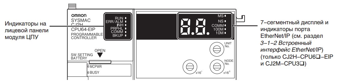
Рис.1.
Рис.2.
Нужна консультация?
Задавайте свои вопросы и получите ответ бесплатно!
Как пользоваться?
Наша цель — обеспечить Вам самый быстрый доступ к руководству по эксплуатации устройства Omron SYSMAC CJ2M-CPU3@. Пользуясь просмотром онлайн Вы можете быстро просмотреть содержание и перейти на страницу, на которой найдете решение своей проблемы с Omron SYSMAC CJ2M-CPU3@.
Для Вашего удобства
Если просмотр руководства Omron SYSMAC CJ2M-CPU3@ непосредственно на этой странице для Вас неудобен, Вы можете воспользоваться двумя возможными решениями:
- Полноэкранный просмотр -, Чтобы удобно просматривать инструкцию (без скачивания на компьютер) Вы можете использовать режим полноэкранного просмотра. Чтобы запустить просмотр инструкции Omron SYSMAC CJ2M-CPU3@ на полном экране, используйте кнопку Полный экран.
- Скачивание на компьютер — Вы можете также скачать инструкцию Omron SYSMAC CJ2M-CPU3@ на свой компьютер и сохранить ее в своем архиве. Если ты все же не хотите занимать место на своем устройстве, Вы всегда можете скачать ее из ManualsBase.
Руководство по эксплуатации Omron SYSMAC CJ2M-CPU3@
Печатная версия
Многие предпочитают читать документы не на экране, а в печатной версии. Опция распечатки инструкции также предусмотрена и Вы можете воспользоваться ею нажав на ссылку, находящуюся выше — Печатать инструкцию. Вам не обязательно печатать всю инструкцию Omron SYSMAC CJ2M-CPU3@ а только некоторые страницы. Берегите бумагу.
Резюме
Ниже Вы найдете заявки которые находятся на очередных страницах инструкции для Omron SYSMAC CJ2M-CPU3@. Если Вы хотите быстро просмотреть содержимое страниц, которые находятся на очередных страницах инструкции, Вы воспользоваться ими.
- Обязательно представиться на русском языке кириллицей (заполнить поле «Имя»).
- Фиктивные имена мы не приветствуем. Ивановых и Пупкиных здесь уже достаточно.
- Не писать свой вопрос в первую попавшуюся тему — вместо этого создать новую тему.
- За поиск и предложение пиратского ПО и средств взлома — бан без предупреждения.
- Рекламу и частные объявления «куплю/продам/есть халтура» мы не размещаем ни на каких условиях.
- Перед тем как что-то написать — читать здесь и здесь.
Замена батарейки в ПЛК
-

Igor NK
- здесь недавно

- Сообщения: 9
- Зарегистрирован: 22 фев 2021, 01:30
- Имя: Игорь Владимирович Ребров
- Страна: Россия
- город/регион: Ставрополь Ставрапольский край
- Благодарил (а): 2 раза


Замена батарейки в ПЛК
Сообщение
Igor NK » 22 фев 2021, 03:23
Контроллер SYSMAC CJ2M CPU12 фирмы OMRON. При включенном оборудовании в ПЛК была отсоедина батарейка, начал мигать красным индикатор ERR/ALM.После установки новой батарейки индикатор не погас.Машину от сети не отключаем.
Подскажите как убрать ошибку?
-

DemoN9577
- осмотрелся
- Сообщения: 129
- Зарегистрирован: 22 июл 2017, 22:47
- Имя: Сергей
- Страна: СССР
- Благодарил (а): 4 раза
- Поблагодарили: 25 раз


Замена батарейки в ПЛК
Сообщение
DemoN9577 » 22 фев 2021, 23:00
Мигающий индикатор указывает на некритические ошибки, при которых CPU продолжает работать. Для начала надо проверить журнал ошибок и выяснить состояние и код ошибки.
Отправлено спустя 4 минуты 13 секунд:
Кстати, по инструкции батарея меняется при выключенном питании…
________________________________
Не ждите чуда — чудите сами!
-
Igor NK
- здесь недавно
- Сообщения: 9
- Зарегистрирован: 22 фев 2021, 01:30
- Имя: Игорь Владимирович Ребров
- Страна: Россия
- город/регион: Ставрополь Ставрапольский край
- Благодарил (а): 2 раза
Замена батарейки в ПЛК
Сообщение
Igor NK » 25 фев 2021, 09:14
Спасибо, подскажите может ли эта ошибка повлиять на программу с последствиями приведущими к неработоспособности машины после отключения от питания сети на длительное время.
Подключиться к ПК нет возможности…
Отправлено спустя 5 минут 17 секунд:
Добавлю, что на дисплее страницы сообщений и ошибок нет.
Ig…
-
Igor NK
- здесь недавно
- Сообщения: 9
- Зарегистрирован: 22 фев 2021, 01:30
- Имя: Игорь Владимирович Ребров
- Страна: Россия
- город/регион: Ставрополь Ставрапольский край
- Благодарил (а): 2 раза
Замена батарейки в ПЛК
Сообщение
Igor NK » 25 фев 2021, 14:25
Разобрался когда прочитал подробную инструкцию. В разных типах ПЛК инструкция по замене батареек может отличаться. Последствия из-за разряда батарейки зависят от того есть карта памяти или нет, а также от модели ПЛК.
Ig…
-
DemoN9577
- осмотрелся
- Сообщения: 129
- Зарегистрирован: 22 июл 2017, 22:47
- Имя: Сергей
- Страна: СССР
- Благодарил (а): 4 раза
- Поблагодарили: 25 раз
Замена батарейки в ПЛК
Сообщение
DemoN9577 » 25 фев 2021, 19:34
Igor NK писал(а): ↑25 фев 2021, 09:19
подскажите может ли эта ошибка повлиять на программу с последствиями приведущими к неработоспособности машины после отключения от питания сети на длительное время.
Так как батарея была отсоединена при включенном питании (скорее всего в режиме run), то скорее всего был взведен флаг ошибки батареи (00F7).
Во избежание повреждения внутренних элементов модуля ЦПУ, чувствительных к
статическому электричеству, рекомендуется производить замену батареи при
выключенном питании. Допускается производить замену батареи без выключения
питания. В этом случае перед заменой батареи обязательно дотроньтесь до заземленного
металлического предмета, чтобы снять с тела электростатический заряд.
Заменив батарею, подключите устройство программирования и сбросьте ошибку батареи.
Если вы уверены в том что батарея исправна, то после перезагрузки журнал активных ошибок должен очиститься. В любом случае, после отключения питания конденсатор какое-то время будет поддерживать питание.
________________________________
Не ждите чуда — чудите сами!
-
Igor NK
- здесь недавно
- Сообщения: 9
- Зарегистрирован: 22 фев 2021, 01:30
- Имя: Игорь Владимирович Ребров
- Страна: Россия
- город/регион: Ставрополь Ставрапольский край
- Благодарил (а): 2 раза
Замена батарейки в ПЛК
Сообщение
Igor NK » 26 фев 2021, 11:16
Спасибо, всё подробно,и понятно.
Ig…
-

Jackson
- администратор
- Сообщения: 15300
- Зарегистрирован: 17 июн 2008, 16:01
- Имя: Евгений свет Брониславович
- Страна: Россия
- город/регион: Санкт-Петербург
- Благодарил (а): 518 раз
- Поблагодарили: 909 раз


Замена батарейки в ПЛК
Сообщение
Jackson » 28 фев 2021, 00:00
Igor NK писал(а): ↑25 фев 2021, 14:25
Разобрался когда прочитал подробную инструкцию
Вообще инструкции лучше читать в первую, а не в последнюю очередь. Ровно для этого они и написаны.
По вопросам работы Форума можно обратиться по этим контактам.
Вернуться в «Средний уровень автоматизации (управляющий)»
Перейти
- Работа форума
- База знаний (Knowledge Exchange)
- ↳ Eplan Electric P8
- ↳ Общий F.A.Q.
- ↳ Общие вопросы
- ↳ Новости
- ↳ Ошибки
- ↳ Проект
- ↳ Изделия
- ↳ Устройства
- ↳ Соединения
- ↳ Кабели
- ↳ Клеммы
- ↳ ПЛК
- ↳ Компоновка 2D
- ↳ Макросы
- ↳ Eplan API
- ↳ Сценарии (Только готовые решения)
- ↳ Внешняя обработка
- ↳ ProPanel
- ↳ Инструкции ProPanel (Только готовые решения)
- ↳ Прочие направления Eplan
- ↳ FieldSys (Топология)
- ↳ Preplanning
- ↳ Harness proD
- ↳ EEC One
- ↳ Advantech
- ↳ F.A.Q., Инструкции
- ↳ Allen Bradley
- ↳ Общие вопросы
- ↳ ПЛК
- ↳ Операторские панели
- ↳ B&R Automation
- ↳ F.A.Q.
- ↳ Danfoss
- ↳ DEIF A/S
- ↳ Общие вопросы
- ↳ UNI-LINE
- ↳ MULTI-LINE
- ↳ MULTI-LINE 300
- ↳ Emerson
- ↳ Общие вопросы
- ↳ КИП и регуляторы
- ↳ DeltaV
- ↳ ОВЕН
- ↳ Прософт-Системы
- ↳ Общие вопросы
- ↳ ПЛК REGUL
- ↳ Schneider Electric
- ↳ Общие вопросы
- ↳ ПЛК
- ↳ Панели оператора
- ↳ SCADA
- ↳ Электротехника
- ↳ Приводная техника
- ↳ SIEMENS
- ↳ Общие вопросы
- ↳ LOGO!
- ↳ ПЛК SIMATIC (S7-200, S7-1200, S7-300, S7-400, S7-1500, ET200)
- ↳ Simatic Step7
- ↳ Simatic TIA Portal
- ↳ Simatic PCS 7
- ↳ Операторские панели
- ↳ WinCC
- ↳ Приводная техника (Sinamics, Micromaster, Masterdrive, Simoreg, Simotics)
- ↳ SmartGen
- ↳ Общие вопросы
- ↳ Промышленные (береговые) контроллеры
- ↳ Морские контроллеры и устройства
- ↳ WEINTEK (операторские панели)
- ↳ F.A.Q., Инструкции
- ↳ Архив
- ↳ Микроконтроллеры и электроника
- ↳ Arduino
- ↳ Другие микроконтроллеры
- ↳ Электроника
- Общие вопросы АСУТП
- ↳ Общие вопросы
- ↳ Вопросы от студентов
- ↳ Литература
- ↳ Новости и отчётность
- ↳ Нормативы, ГОСТы, стандарты
- ↳ Информационная безопасность
- ↳ Проектирование и САПР
- ↳ Системная интеграция
- ↳ Разбор полетов
- ↳ Работа
- ↳ Заготовки для базы знаний
- ↳ Производство и технология
- ↳ MES — Системы автоматизации управления производством
- ↳ Метрология, КИП и датчики
- ↳ Исполнительные устройства, регуляторы
- ↳ Средний уровень автоматизации (управляющий)
- ↳ Алгоритмы
- ↳ Операторские панели
- ↳ Верхний уровень автоматизации (отображение)
- ↳ GE iFix
- ↳ Wonderware Intouch
- ↳ MasterScada
- ↳ SCADA+
- ↳ Alpha.Platform
- ↳ Интерфейсы, протоколы, связь
- ↳ Радиосвязь
- ↳ Полезное ПО
- ↳ Электротехника, энергетика и электропривод
- ↳ Генераторы и электростанции
- ↳ Теплотехника
- ↳ Подбор аналогов
- F.A.Q. (краткая выжимка из некоторых сообщений форума)
- ↳ Электротехника и электроэнергетика
- ↳ Документация
- ↳ Общие вопросы
- ↳ Оформление документации
- ↳ Нижний уровень автоматизации
- ↳ Средний уровень автоматизации
- ↳ Верхний уровень автоматизации
- ↳ Интерфейсы, протоколы, связь
- ↳ Функциональная и промышленная безопасность
- ↳ Электротехника и энергетика
- ↳ Автоматизация предприятия
- ↳ Описания средств автоматизации
- ↳ F.A.Q. по программируемым логическим контроллерам (PLC)
- ↳ Обсуждение F.A.Q. по PLC
- ↳ F.A.Q. по выбору PLC
- ↳ F.A.Q. по аппаратной части PLC
- ↳ F.A.Q. по языкам программирования
- ↳ F.A.Q. по структуре программ
- ↳ F.A.Q. по взаимодействию PLC с HMI
- О жизни
- ↳ Для дома, для семьи
- ↳ Комната смеха
- ↳ Электродвижение